The last frontier: VTOL
Flight Journal, Jun 2003 by Robert Kress
The Ups and Downs of Vertical Takeoff and Landing
This is my insider's look at the sometimes frustrating world of creative aerodynamics and the difficulties associated with getting a new design concept adopted. Two decades or so ago, Grumman had an idea that we thought would fill a national need, but it was not to be. Politics doesn't always understand the rationale behind technical progress. Today, the idea in question is still viable. The national need for it is still unsatisfied. So, this old engineer soldiers on.
Since the laws of physics refuse to bend for anyone, we engineering types are reaching the point of diminishing returns with much of our design work. For instance, the progression from the Wright Flyer to Spads to Mustangs to Tomcats represents enormous strides, but since the F-14/F-15-type aircraft came on the scene, we've been bumping our heads against technological ceilings. Does the absolutely state-of-the-art F-22 represent the same progression as we saw from Mustang to F-86? Of course not. Does it offer anything hugely different from its predecessors? No, it doesn't. It does, however, improve the breed, but it doesn't redefine it.
So, have we seen all there is to see with respect to the development of flying machines? Here, too, the answer is no because at least one frontier hasn't been efficiently conquered: vertical takeoff and landing (VTOL). VTOL represents the last frontier primarily because, although we've poked our toes into those aeronautical waters, with the exception of helicopters, we really haven't waded all the way in and learned to swim. For the most part, we have retreated to the shore when we found the going tougher than we expected.
VTOL
A ton of VTOL aircraft (not helicopter types) have been invented and some were even tested as full-scale prototypes. Seth Anderson of NASA-Ames constructed a wonderful "pinwheel" chart, later named the "wheel of misfortune," that presented all of the VTOL configurations tested up to about 1980 (there haven't been many since then). Some flew without crashing. Some were inventors' dreams. Some attempted to defy the laws of physics and suffered the consequences. However, with the exception of the Harrier and the XV-15 (V-22 prototype), nothing came of them.
WHY?
When you study most of these aircraft knowing what we know now, it's obvious that they were technically flawed. The most obvious problems included inadequate control authority in hover, mechanical complexity, poor structural integrity, erratic stability and control during transition and that they had to try to lift too much weight with too little thrust.
It's important to understand the history of VTOL aircraft in terms of the principles of aerodynamics. Thrust-per-shaft-horsepower in VTOL aircraft is determined by the amount of horsepower applied to the tube of air being accelerated by the powerplant. Power could come from a reciprocating engine ducted fan, a jet engine or a turbofan. As long as the horsepower is there-it could be generated by a rubber band-the column of air doesn't care.
At the low-disc loadings typical of helicopters (that is, the weight the disc is required to lift measured in pounds per square foot of disc area), the thrust produced per input-shaft horsepower is very high. Aircraft in this class lift large loads, have long hover duration but not enough downwash to chew up the ground as a jet does. Their speed, endurance and ceiling are generally much lower than the higher-disc-loading vehicles. A good modern example of low-disc loading was the XV-15 (which became the V-22 Osprey). At the other end of the disc-loading spectrum is the lowbypass turbofan AV-8 Harrier. This thing is really loaded! The Harrier made the concept work but not without paying a price: high fuel flow in hover. Airshows excluded, Harrier pilots don't want to hover for long, or they'd better hover right over to a gas station.
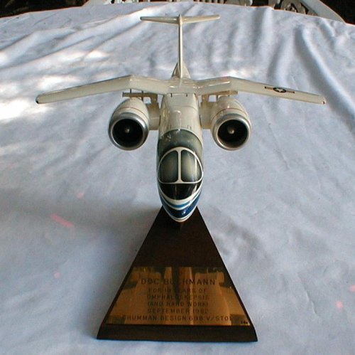
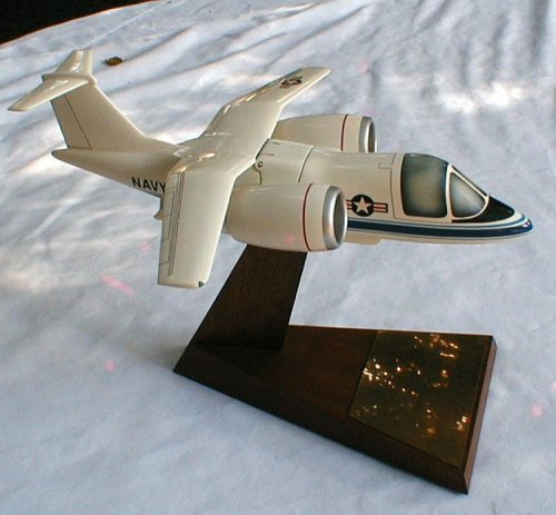
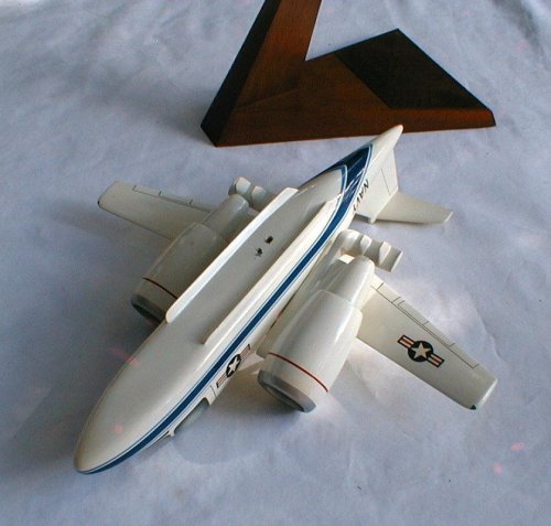
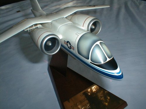
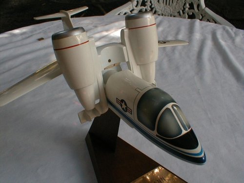
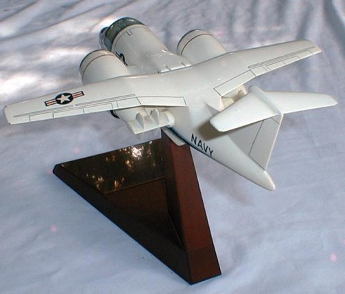
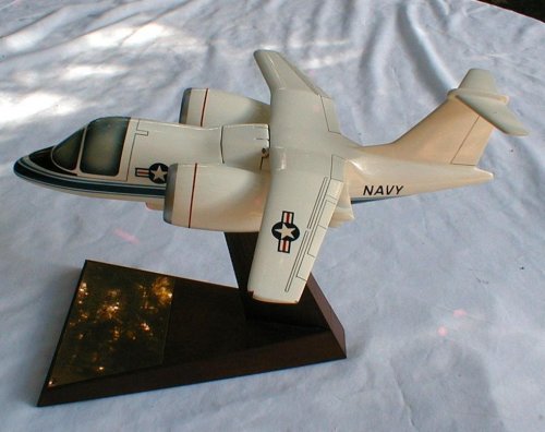
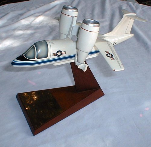
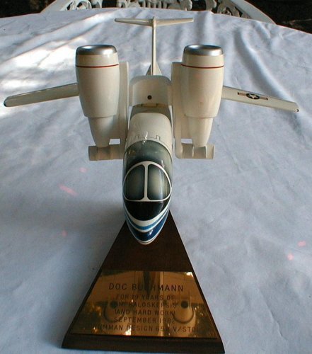
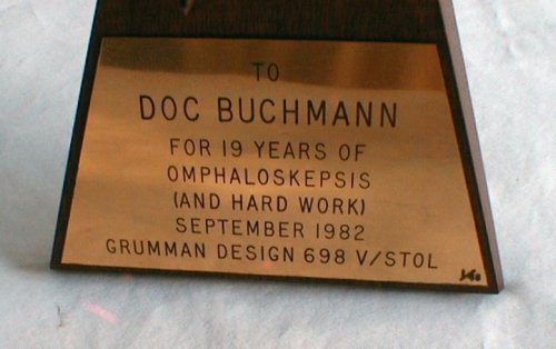
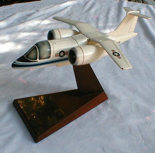
If all of the VTOL concepts, those that have been proposed and those that have flown, are compared, it would be noticed that there is a distinct gap between the lightly loaded birds and those that carry a lot of weight on a small disc. This gap indicates that little effort has been expended on developing VTOL turbofan transport-type aircraft, with one exception-Grumman's Design 698 Tilt Fan VTOL. The goal of Design 698 was to fill this gap with a Learjetclass, high-speed, long-endurance and high-altitude aircraft that would also have USN surface-combat applications. A lot of work was done on the 698 and, considering that the niche for which it was designed still exists, more needs to be done on this and other promising turbofan VTOL concepts. If we could just get our VTOL act together, the payoff could be huge in terms of highly versatile civil and military aircraft.
Grumman started blasting away at the last frontier in the early '70s. I was the primary player along with a couple of other fugitives from the lunar module (LM) program. Our first concept was the Nutcracker.
IN THE BEGINNING THERE WAS THE NUTCRACKER
o fully savor the essence of the Nutcracker, look at the photo above. If you don't exclaim, "What is that?" you're one of the few who don't. It is exactly what it appears to be:
* a VTOL aircraft that folds in the middle;
* a VTOL aircraft attempting in-flight docking on a destroyer.
Regardless of how weird it looks, the space guys had a reasonable aircraft concept. The VTOL breaking in half cured all of the ills associated with the "tail-sitter" VTOLs (they had to reverse into a landing tail first), which were:
* poor visibility for pilot;
* wing stall during transition when the wing had to plow through the high-angle-of-attack regime, usually with serious stability and control problems;
* when they are hovering, they present their entire profile to the wind, so gusts can blow them all over the place; this makes precision maneuvering difficult, particularly at sea and over oil rigs.
A benefit of the seemingly strange configuration was that the Nutcracker could make conventional takeoffs and landings with the fuselage unbent. We had created a "perch sitter"essentially, the Nutcracker came in like a hovering hummingbird and plugged into its landing nest.
The Nutcracker was not small. It was designed for antisubmarine warfare (ASW) and ocean surveillance/attack roles. On hot days, takeoff gross weight (TOGW) was 21,500 pounds. For attack, the Nutcracker could carry one harpoon missile. Powered by two cross-shafted GE TF-34 engines, it could hit 500 knots and 45,000 feet and it had a 400nautical-mile-radius of action. The cross-shaft provided engine-out control in transitional flight. We had put a lot of thought into our strange-looking creation.
We conducted extensive hover and conventional-flight radio model tests and realistically simulated the docking procedure. To answer questions about how the tail would work while being beaten to death by the engine blast, we tested an A-6 stabilizer behind a Hamilton Standard T-55 Q-fan engine.
THE USN WAS LOOKING FOR ANSWERS
Between 1973 and 1975, substantial USN/NASA activity was devoted to design and to small-scale testing of what were known as lift-fan vertical/short takeoff and landing (VSTOL) concepts. In 1976, CNO Adm. James L. Holloway III announced a bold new USN program that would lead to two new types of VSTOL aircraft. A "Type A" utility class would be developed first, and a "Type B" fighter class would follow. The object was to deploy a large number of combat aircraft on various combat ships (destroyers, etc.) rather than to cluster them all on carriers. This would make air operations more flexible, and it would be harder for the bad guys to nail a lot of airplanes at one time.
A single Type A aircraft would replace a bunch of conventional carrier aircraft. The grand plan was that one basic VSTOL airfrarne would replace E-2, C-Z, S-3 and EW types and the USMC H-46 helos. Obviously, this would be a very big ball game.
And where was Grumman while all of this was going on? We were working on a "perching" bird that was as simple as all get out but useless for the tasks at hand because it needed a special apparatus to land. It was time to change direction.
ENTER SON OF NUTCRACKER
At Grumman, our first objective in VSTOL design was always simplicity, and we asked ourselves how we could retain the simplicity of Nutcracker while getting it off its perch. We had to make it compatible with ship decks without having the special gear needed to land it. The answer came when we reflected on the Nutcracker's control power, which was very large about all three axes owing to the long tail length of the surfaces immersed in the fan blast. We designed a configuration in which tilt nacelles rotated about the wing's leading edge and had horizontal and vertical vanes in the fan blast. These were hung as far below the airplane's center of gravity (CG) as they could be and still use a reasonably long landing gear.
Our initial calculations indicated that we could more than meet USN control power specs, but we had to prove it. To turn theory into reality, we built a full-scale "iron monster" test rig next to the Bethpage runway. Essentially, it was a huge bed frame with a Hamilton Standard T-55 Q-fan mounted horizontally with control vanes (almost like Venetian blinds) in the jet blast at the proper locations. Our estimates of vane lift and drag were verified by this rig's performance, but we certainly killed a lot of grass in the process.
We kicked around a lot of names for the new design, and "short-tailed Nutcracker" was just too much to say easily; besides, it sounded like an exotic bird. We settled on Design 698, which existed in several configurations. The earliest version of 698 had a canard up front that was changed to a tailed configuration when we discovered that the fan cowls acted like ring wing canards. This was a fortuitous turn of events that resulted in high-speed airflow through the cowls, making the cowls themselves act like endless wings.
THE TILT-FAN ROADSHOW
We at Grumman had a late start in the Type A VSTOL ball game, but we launched an intensive and rather different promotional campaign. A large, radio-controlled, tethered, hover model was constructed by Nick Ziroli of model fame and was demonstrated at every government facility that would let us on its grounds. The tether was there to save the model in the event of an engine failure, which happened only once in roughly 100 demo flights.
While the airplane was flying, a "barker" provided a colorful commentary on what was going on and kept up the excitement level up. We had everything but dancing girls. The whole thing was known as "Baron von Kress flying circus." Among other places, the "circus" went to NASA-Ames, the Naval Air Development Center and the Naval Air Test Center.
Our highest-profile demonstrations were when we rented the Butler Aviation Hangar at Washington National Airport for one week and flew three demonstrations every day (preceded by the usual barker on the PA system extolling the virtues of our design). Grumman bussed military and civilian personnel from all over O.C. and charged them 50 cents a bus ride to keep it all legal. Hey, when you market at this level, you have to stretch the boundaries if you expect to be noticed.
Perhaps the strangest 698 flight demo was the one in Grumman Calverton's huge anechoic chamber that deadens sound. As I started my preflight talk, I realized that there was absolutely no sound feedback, and I couldn't hear my own voice; I wasn't sure whether I was making any sound at all. I was more unhinged than usual, and the model sounded as though it were rubber-powered instead of powered by two screaming model engines.
DESIGN 698 EMERGES
As is the case with many government programs, the Type A VSTOL faded from view, but that didn't faze us in the Nutcracker suite. We continued as if nothing had happened, and in the process, we refined the 698's design.
* The canard became a horizontal tail.
* A simpler and more producible way to hang the engines was invented; they were mounted on the ends of a wing leadingedge cross-member that could be rotated.
* Strakes added to the lower fuselage were carefully designed with respect to angle and length to effectively control the downward blast that bounced off the ground.
* Vertical vanes were installed in the jet blasts for roll control; they replaced the variable inlet guide vanes that had been added earlier for thrust modulation.
* A new landing gear was designed and optimized for operations off rolling, pitching carrier decks.
From about 1978, we concentrated on putting high-performance surveillance/attack aircraft on surface combatants. Also, the idea of a small Learjet-class VTOL seemed very attractive. We envisioned a 20,000-pound-class aircraft with two TF-34 turbofans. At the time, there was skepticism about the 10,000-pound-thrust output of the TF-34s for the application. Today, one can buy CF-34s rated at 14,500 pounds, which will shortly be upgraded to 18,500.
698 FLIGHT DEMONSTRATOR PROGRAM
By 1978, there was enough interest in the project for us to obtain USN R&D funding. A vigorous program funded by NASA and Grumman was set in motion; it built on the progress already made in 698 Type A work.
One interesting test involved piloted flight through transition by using a radio-controlled model on the end of a 50-foot whirling arm rig. The Grumman Research Department constructed an extremely light whirling arm that was inflated to 200psi for stiffness and had gossamer guy wires. Its function was to restrain the model's centrifugal forces without corrupting its mass and inertia. Nick Ziroli sat on a whirling chair and flew the model with throttle and vane control. The effects on Nick were the subject of much mirth; he survived, but he still walks a little funny!
The program's crowning achievement was the construction of a full-scale, 43,000-pound test model of the 698. It was tested in NASA Ames' 40x80-foot wind tunnel and was later the first unit tested in the new 80x120-foot test section.
WHAT'S IN THE FUTURE
The full-scale Design 698 was exhibited in the Great Hall at the 1981 Paris Air Show. It had completed more feasibility and proof-of-concept testing than was usual; it had reached the point at which a flight demonstrator would be a reasonable proposal, and much of Grumman's work focused on that.
Also, at the Paris Air Show, however, was the XV-15 tilt rotor, and it flew morning and afternoon shows with all sorts of precious human cargo on board. Predictably, the proposal to build the JVX won strong NASA support. The 698 was perceived to be a threat to the development of the JVX (later known as the Osprey). This aircraft was for USMC use, and our design did not fit the operational missions envisioned because its jet blast was too fierce. No government thought was given to anything other than the Marines' needs, even though there were lots of obvious other VTOL applications.
Nevertheless, Design 698 shriveled "like a salted slug," as P.G. Wodehouse once put it. Flashing ahead to today: maybe now, with the Osprey's poor track record and the tilt-rotor concept behind us, it is time to move forward with a Nutcracker variant. The VTOL niche is still vacant, and the Design 698/Nutcracker technology is still there.
Who would build a new VTOL design? Not Grumman, obviously; it has long gone. Still, there is money to be made and a service to be rendered to the country. Who would profit? Not me. But, you know the saying, "Old engineers never die ..."? Well, you can't get us to shut up either!

