Kayaba Projects and Prototypes

blackkite

Don't laugh, don't cry, don't even curse, but.....
Joined
31 May 2007
Messages
8,603
Reaction score
6,880
Kayaba Katsuodori ramjet interceptor was a Kayaba's private project planned in 1943.
Second picture shows Unicraft model's Katsuodori.
http://www.unicraft.biz/on/kayaba/kayaba.htm


Span : 9.0 m, Length :4.5 m, Wing Area :13.50 , Wing sweep back angle :25.5 °, Gross weight :3000 kg, Empty weight : 800 kg,
Main engine : ramjet engine,M 0.3;300 kg,M 0.5;550 kg, (M 0.60.9;750 kg, Take off engine : Rocket engine : thrust 7200kg,
Maximum speed ;900 km/h, Service ceiling ;15000 m, Climb time ;3minutes/10,000 m, Endurance ; 30 min, Range ;400 km,
Armaments ; 30 mm cannon×2
 

Attachments

  • Kayaba_KatsuoDori 3 side.jpg
    Kayaba_KatsuoDori 3 side.jpg
    33 KB · Views: 702
  • kayaba-katsuodori.jpg
    kayaba-katsuodori.jpg
    163.6 KB · Views: 676
My dear Blackkite,


in 2006 a friend sent to me this Kayaba Katsoudori 3-view drawing picture,but
it has a different cockpit.
 

Attachments

  • kayaba katsuodori.jpg
    kayaba katsuodori.jpg
    91.9 KB · Views: 646
Katsuodori means gannet.
 

Attachments

  • Gannet.JPG
    Gannet.JPG
    39 KB · Views: 101
Kayaba Type 4 flying wing Aircraft
The Kayaba factory started the development of Kayaba type 4 aircraft as a reply to the request from the army aviation technology research institute of "To manufacture a flying wing light aircraft with engine", and the wind tunnel test by Hidemasa Kimura of Aviation Research Institute of Tokyo Imperial University showed good characteristic of type 4 aircraft.
The mock-up was carried forward in the Ito airplane factory, and the drawing completed at the end of April, 1941. It is a single-seater plane with a Gypsy major engine (120 HP).
Since it is not described by recollection of Mr. Shiro Kayaba, but perhaps the development started in 1940. Although the relation between type 4 and type 2 or 3 are also unknown, but it's difficult to install engine to type 2 or the type 3 aircraft, new design as type 4 aircraft was needed.
In addition, although type 4 aircraft had a engine, the IJA gave the name Ku-4 which means the IJA's glider. Moreover true or not, in Mr. Kayaba's reminiscences, once the name Ki-60 was assigned to type 4 aircraft, temporally overlapped with Kawasaki Ki-60.
The army aviation technology research institute made an attitude turn one's coat taking account of the type 2 accident in Tachikawa on May 10, 1941 after type 4 aircraft's drawing completion.
The IJA grudged experimental manufacturing cost of 100,000 yen(about 7 million USD now) for type 4 aircraft.

It seems that that the budget of the test prototype was reduced since priority was given to the actual weapon aircraft development and production. The accident of type 2 was only a cause.
The type 4 aircraft finished after all, without being manufactured, and since it was difficult also as a Kayaba factory to further development at its own expense from the first, the flying wing aircraft series of Kayaba suffered a setback.
Although 17,000 yen is provided as type 1 through type 3 aircraft manufacture expense from the army aviation technology research institute, but it was large in the red as Kayaba.

Span ; 9.8m(same asa type 2 aircraft), Length ; 3.42m, Height ; 1.86m(except propeller), Wing area ; 13.3 square meter, Dihedral ; 6 degree, Wing sweep back angle ; 26.5 degree, Gross weight ; 650kg, Empty weight ; 515kg, Maximum speed ; 180km/h, Cruising speed ; 150km/h, Endurance ; 2hours, Range ; 300km
Source ; internet
 
Thanks Blackkite for the information on the Ku-4!
I have a question concerning the Kayaba Ku-2:
The only photo I found of this glider seems to show a straight (or very slightly swept) wing (or perhaps it's a visual distorsion). But a 3V drawing published in a post-war US Air Technical Intellingence Report shows a clearly swept wing.
Is there some confirmation about the type of wing used on the Ku-2 (or more photos of this glider available)?
 

Attachments

  • 10.jpeg
    10.jpeg
    10.2 KB · Views: 123
  • Kimura005A.jpg
    Kimura005A.jpg
    93.5 KB · Views: 141
Retrofit said:
Thanks Blackkite for the information on the Ku-4!
I have a question concerning the Kayaba Ku-2:
The only photo I found of this glider seems to show a straight (or very slightly swept) wing (or perhaps it's a visual distorsion). But a 3V drawing published in a post-war US Air Technical Intellingence Report shows a clearly swept wing.
Is there some confirmation about the type of wing used on the Ku-2 (or more photos of this glider available)?
Ok! I will check it. Give me time.
 
Kayaba Katsuodori
Kayaba Katsuodori was a fighter plane for high altitude interception which the Kayaba factory planned. The Kayaba factory had been developing the flying wing reaction engine aircraft gaining assistance of the IJA from 1936, and the final objective was Katsuodori.
Although Kayaba manufactured the non-power glider for checking the aerodynamic characteristic of the aircraft, the test pilot of the army side who did not understand the operation characteristic of a flying wing aircraft causes an accident during a test, and development is stopped.
In addition, Hidemasa Kimura famous designer who developped YS-11, etc. took charge of series of Kayaba gliders made as an experiment.
Katsuodori had a sweep back wing with comparatively high aspect ratio and had the vertical stabilizer which attached the rudder at the wing tip.
Kayaba type 1 ram jet engine(thrust ; 750kg) was installed in the fuselage, and the drop type two sets takeoff promotion rocket (total thrust ; 7200 kg) were located each side of the fuselage.
Probably a rocket performs a takeoff and initial acceleration, and it seems that the ram jet engine would be scheduled to be put into operation in the place which reached the speed that sufficient ram pressure is generated. Armaments were 30mm unreacted cannons located in the wing.
Neverthleess having Shusui comparable performance (maximim speed ; 900 km/h, service ceiling ; 15000m), special rocket fuel/engine like Shusui and complicated turbine engine like Kikka were not needed. Katsuodori was a ideal interceptor at the day.
Probably, military-power-izing was possible in 1945, when developped earnestly.

Source ; internet
 
Hi Retrofit!
Are these pictures what you need?
Some document says that the sweep back angle of Ku-2 wing was 25.5 degree.
Also some document says that Ku-2 was for a fighter, Ku-3 was for a long range twin engine aircraft.

Ku-2 specification.
Span ; 9.8 m, Length ; 3.04 m, Wing root chord length ; 1.8 m, Wing tip chord length ; 0.75 m, Wing sweep back angle ; 25.5 °, Wing area ; 14.5 ㎡, Vertical stabilizer total area ; 2.323 ㎡, (Rudder area)1.380 ㎡, Empty weight ; 124 kg, Wing loading ; 13.4 kg/㎡, (pilot weight ; 70kg)Best gliding speed ; 75 km/h
 

Attachments

  • kayaba glider pic 3.jpg
    kayaba glider pic 3.jpg
    275.9 KB · Views: 145
  • kayaba glider.jpg
    kayaba glider.jpg
    186.8 KB · Views: 127
Definitively swept wings...
Thanks a lot Blackkite for those photos!
 
Not at all Retrofit. ;)
Do you hava Ku-3 pictures?
 
blackkite said:
Not at all Retrofit. ;)
Do you hava Ku-3 pictures?
Just this one I found on internet (but no valid 3V drawing):
 

Attachments

  • ku3-1a.jpg
    ku3-1a.jpg
    42.9 KB · Views: 125
Thanks! Super. :D
 

Attachments

  • kayaba Ku-3.jpg
    kayaba Ku-3.jpg
    207.7 KB · Views: 142
Found this
 

Attachments

  • KN_1941_Flywing_Draw_Mini_Kayaba Ku3.jpg
    KN_1941_Flywing_Draw_Mini_Kayaba Ku3.jpg
    86.7 KB · Views: 531
Wow! Thanks for sharing us. :eek:
What a complicated wing shape.
I understand that Kayaba type 4 was Ku-4.

Kayaba type 3
http://www2s.biglobe.ne.jp/~FlyWing/JapaneseTaillessPlane/Kayaba-3.html
Kayaba type 1
http://www2s.biglobe.ne.jp/~FlyWing/JapaneseTaillessPlane/Kayaba-1.html
Kayaba type 2
http://www2s.biglobe.ne.jp/~FlyWing/JapaneseTaillessPlane/Kayaba-2.html

Following pictures shows Kayaba H.K. type aircraft. It's perhaps Kayaba type 1 aircraft.
H.K. means Hidemasa Kimura, the designer of this aircraft.
Source
http://vsha.jp/page99.php
 

Attachments

  • kayabahk-7.jpg
    kayabahk-7.jpg
    368 KB · Views: 129
  • kayabahk-5.jpg
    kayabahk-5.jpg
    178.2 KB · Views: 110
  • kayabahk-4.jpg
    kayabahk-4.jpg
    161 KB · Views: 107
  • kayabahk-3.jpg
    kayabahk-3.jpg
    875.9 KB · Views: 419
  • kayabahk-2.jpg
    kayabahk-2.jpg
    182.5 KB · Views: 444
  • kayabahk-1.jpg
    kayabahk-1.jpg
    469.9 KB · Views: 485
Fabulous stuff blackkite! First time I've seen the Ku-10. Thanks a lot! :)
 
If you look at the 3 view diagrams and other pictures of the Katsudori it doesn't look like there is enough room in the aircraft for both the air intake and the cockpit. Does anyone have a drawing of the internal layout?
 
Hi! Sorry for poor one.
Star! I'm very happy that you enjoyed my post. :)
 

Attachments

  • Katsuodori.jpg
    Katsuodori.jpg
    208.8 KB · Views: 130
  • Kayaba_KatsuoDori 3 side[1].jpg
    Kayaba_KatsuoDori 3 side[1].jpg
    49.1 KB · Views: 134
Cannot really interpret the boxart/artist impression in relation to the pilots position,
but that thing above the engine intake is a lounger for the prone pilot ?
Otherwiese he could only have had a "Münchhausen" like ride on that engine. ;)
(picture from http://euro-med.dk/billeder/billederbaronmuenchhausen-hansalbers29.jpg )
 

Attachments

  • muenchhausen.jpg
    muenchhausen.jpg
    16.5 KB · Views: 102
Jemiba said:
Cannot really interpret the boxart/artist impression in relation to the pilots position,
but that thing above the engine intake is a lounger for the prone pilot ?
Otherwiese he could only have had a "Münchhausen" like ride on that engine. ;)
(picture from http://euro-med.dk/billeder/billederbaronmuenchhausen-hansalbers29.jpg )
HA,HA.... Thanks Jens!
Next picture from MENG MODEL. I wonder the ground clearance.
Is it launching position?
 

Attachments

  • 10169997z5.jpg
    10169997z5.jpg
    62.1 KB · Views: 155
  • Hiryu.jpg
    Hiryu.jpg
    205.3 KB · Views: 154
  • Renzan.jpg
    Renzan.jpg
    286.2 KB · Views: 119
blackkite said:
Next picture from MENG MODEL. I wonder the ground clearance.
Is it launching position?

Certainly, at least, as long, as the Ki-67 wouldn't have used the Katsudori landing gear ! ;)
(the line beneath the side view marks the ground clearance)
I think, it would have been retracted into the bomb bay, just as in the case of the G4M with the
Okha, but not simply dropped, but lowered with a rack to start the engine prior to launch.
 

Attachments

  • Ki-67.JPG
    Ki-67.JPG
    4.6 KB · Views: 315

Attachments

  • img003.jpg
    img003.jpg
    35.8 KB · Views: 122
  • Ku-6 artistic impression.jpg
    Ku-6 artistic impression.jpg
    326.5 KB · Views: 117
  • Antonov_A-40.jpg
    Antonov_A-40.jpg
    111 KB · Views: 96
  • AntonovA40.jpg
    AntonovA40.jpg
    21.5 KB · Views: 99
  • Ku-6.jpg
    Ku-6.jpg
    48.3 KB · Views: 162
The configuration of the Ku-6 tank glider
is not that clear it seems...?
 
So, any further information on the cockpit position?

The Meng model places a turbine blade disk immediately inside the nose inlet. While being entirely wrong for a ramjet, leaving it off would reveal the unfaired cockpit tub assembly. I originally though the large hump behind the cockpit was actually part of the cockpit - this, much like the Skoda Kauba SK P.14.01. But apparently, the pilot's position was not prone and thus the inlet had to have been trunked around the cockpit "tub."

Any further details on what that might've looked like?
 
lark said:
The configuration of the Ku-6 tank glider
is not that clear it seems...?
Yes it is.
But perhaps the wings of No.1 picture and No.5 picture were very hard to have enough wing root strength for bending moment due to lift.
These wing shape need heavy weight large flange and many bolts at the wing root. It took many time to remove the wing from the tank.
And thanks Madoc. ;)
 
Katsuodori was a ram jet fighter which the Kayaba factory developed independently. The Kayaba factory began to develop the ram jet engine from 1937 and the design of the ram jet engine was completed in 1943. Katsuodori flying wing fighter was designed to have this ram jet engine. The wing of Katsuodori was a swept wing based on the wing of the Ku 2 type glider, and the vertical tail was attached to the both-wings tip. The ram jet engine which was the main power was stored in the fuselage, take the air from the nose of the aircraft, and discharged combustion gas from the tail of the aircraft. The auxiliary power for putting a ram jet engine into operation was the gunpowder rocket attached to the both sides of the fuselage. The gunpowder rocket consisted of a total of four of every two right and left. When Katsuodori departs, first, every one right and left and a total of two gunpowder rockets were lit, and it takes off, and drops these two gunpowder rockets burned out 5 seconds afterward. When the two remaining gunpowder rockets were lit simultaneously and these two gunpowder rockets were burned out 10 seconds afterward, the speed of fighter plane arrived at Mach 0.3 order. At this time, Katsuodori lights a ram jet engine, go abruptly up to an altitude of 10000 meters, and it glides when air battle, and returns to a base. The climbing time up to 10000 meters was short and the battle time in 10000 meters was 30 minutes, Katsuodori was far advantageous compared with Shusui rocket fighter. When Katsuodori was put in practical use, it must have become an epoch-making interceptor. However, although the mechanism was easy, the ram jet engine needed delicate operation for operation, and in order to put in practical use, there were many problems which must be solved. Since Katsuodori did not have the prospect of the budget, it did not realized.
Source ; All the Experimental Aircrft in Japanese Army. ISBN978-4-87357-233-8
 
blackkite said:
Katsuodori was a ram jet fighter which the Kayaba factory developed independently. The Kayaba factory began to develop the ram jet engine from 1937 and the design of the ram jet engine was completed in 1943. Katsuodori flying wing fighter was designed to have this ram jet engine. The wing of Katsuodori was a swept wing based on the wing of the Ku 2 type glider, and the vertical tail was attached to the both-wings tip. The ram jet engine which was the main power was stored in the fuselage, take the air from the nose of the aircraft, and discharged combustion gas from the tail of the aircraft. The auxiliary power for putting a ram jet engine into operation was the gunpowder rocket attached to the both sides of the fuselage. The gunpowder rocket consisted of a total of four of every two right and left. When Katsuodori departs, first, every one right and left and a total of two gunpowder rockets were lit, and it takes off, and drops these two gunpowder rockets burned out 5 seconds afterward. When the two remaining gunpowder rockets were lit simultaneously and these two gunpowder rockets were burned out 10 seconds afterward, the speed of fighter plane arrived at Mach 0.3 order. At this time, Katsuodori lights a ram jet engine, go abruptly up to an altitude of 10000 meters, and it glides when air battle, and returns to a base. The climbing time up to 10000 meters was short and the battle time in 10000 meters was 30 minutes, Katsuodori was far advantageous compared with Shusui rocket fighter. When Katsuodori was put in practical use, it must have become an epoch-making interceptor. However, although the mechanism was easy, the ram jet engine needed delicate operation for operation, and in order to put in practical use, there were many problems which must be solved. Since Katsuodori did not have the prospect of the budget, it did not realized.
Source ; All the Experimental Aircrft in Japanese Army. ISBN978-4-87357-233-8

this topic is as usually very awesome blackkite san! Idid not know that Japan als was working on a ramjet type engine.and this has a advantage compared with a rocket engine!
The Katsuodori was if it was build the first ramjet fighter ever much better than the Messerschmidt ME-163,who has a combat time of 5 minutes compared with the Katsuodori who's combat time was 30 minutes!
If the Germans possessed this design the US having a bad time above Europe and if the Japanese having this plane on time much more B-29s meet their end on Japanese soil
 
I have one question here: were Kayaba and Maeda the same company, as the recent regrouping of certain posts seems to imply?

Thanks for your help.
 
I think that I mistook the topic destination to which I should post.
 
Kayaba's main aircraft line was a series of autogyros based on the Kellett KD-1A.

The Japanese bought the Kellett and damaged it.
Kayaba rebuilt it as the Ka-Go.
The Ka-1 was the production version.
The Ka-2 was a re-engined variant of the Ka-1.

At least, that's what Wikipedia says.
 
Kayaba Katsuodori

Despite their appearances, the short range of the airplanes powered by rockets seriously hindered its military use. The logical alternative was to favour the development of the turbojet to achieve more reliable and powerful engines. Unfortunately, the Japanese industry was not able to produce the required metallic alloys, especially resistant to heat and stress. They lacked metals like chromium and molybdenum that were essential to harden the steel.


But the advanced materials for the compressor blades of the turbojets would not be ready on time and everyone was aware of it. The Maru Ka-10 pulsejet did not have power enough and it was soon made evident that they were a death end. The vibrations they generated were destructive to the airplane structure. The situation demanded a new type of engine capable of running on any fuel and easy to build with cheap metals, so the Japanese aircraft industry was forced to consider the use of ramjets.

The theory elaborated by René Lorin in 1913 established that this type of engines produced the maximum thrust at Mach 2, but the theoretical work carried out in Germany by Dr. Eugen Sänger in 1940 showed that a ramjet built with length/diameter ratio of 5 to 1 could work in the high subsonic speed range, with lower specific fuel consumption than a rocket and higher thrust than a turbojet.

In the forward conical portion of the engine, the air flow will be decelerated with simultaneous pressure increase to approximately one-sixth of the flight speed. In the cylindrical combustion chamber the fuel is injected according to the throttling and mixed with the flowing air. At a speed above 200 kph the air inlet pressure is enough to start ignition using a ring of spark plugs, with the gases ejected from the jet pipe at a superior speed than that of flying. The first tests carried out in 1941 in the LFA-Volkenrode produced very long flames which discouraged wind tunnel test with ramjets. Ground test began in autumn 1941 with a prototype mounted above the Opel-Blitz truck.

In March 1942, a Sänger ramjet with 500 mm diameter was tested in flight, mounted above a Dornier Do 17 Z bomber, provided by the DFS-Ainring Institut. In December, a second test was carried out with a ramjet of 1,500 mm mounted above a Dornier Do 217 E-2. In the summer of 1944, the same airplane was used to test the final version of 1,000 mm. The ramjet worked correctly every time, although with low thrust due to the low speed of the bomber.

In theory, the Sänger 1000 had a nominal output of 17,400 hp, the Sänger 1,500 of 22,000 hp and the Sänger 2000 of 61,000 hp. But this could only be demonstrated by installing them on an aircraft capable of flying at a speed of Mach 0.8 and an altitude of 15,000 m. In January 1945 the DFS Institut issued a report suggesting the mounting of two Sänger 1000 above the wings of a Me 262 A-1. It was expected an increase of 200 kph in maximum speed, an increase of 4,000 m absolute ceiling and the reduction of the climbing time to 10,000 m from 26 to 6 minutes. The plan was thereby frustrated by the shortage of J2 fuel available for flying tests.

On 30 November 1944, the RLM requested the design of a ramjet propelled fighter. In December, the Oberammergau project bureau started working on a version of the Messerschmitt P.1101 powered by a Sänger 1000 in anticipation that the HeS 011 turbojet would not be ready on time. The modifications consisted in increasing the diameter of the fuselage, installing three fuel tanks of 1,500, 500 and 120 litres and designing a new landing gear whose main wheels would retract in tandem under the engine. The take-off was effected with the help of eight detachable RATO rockets of the Schmidding type 109-533, with 1,000 kp peak thrust each, which accelerated the aircraft to 120 m/sec. The new version was called Messerschmitt P.1101 L (Lorinantrieb).

In December 1944, Professor Sänger designed the Überschall-Staustrahljäger (supersonic ramjet fighter), a high-altitude interceptor of 7 tons propelled by a ramjet of 60,000 hp, but the DFS Institut lacked the facilities for its construction. In February 1945, the firm Skoda-Kauba Flugzeugbau-Cakowitz, who had carried out some discouraging experiments with foam coal ramjets, issued an order to the RLM for the design of an interceptor with ramjet propulsion based on the theoretical work of Sänger.

On 25 February 1945, the company produced the SK P14-01 design, a Mach 0.815 fighter powered by a Sänger 1500 with 22,000 hp nominal thrust, 1,000 litres of fuel, pilot in prone position, one MK 103/30 heavy cannon, landing skid and 10,000 m estimated absolute ceiling. The definitive design dated in April was the 7-tone SK P12-02, powered by a Sänger 2500 with 60,000 hp nominal thrust, 1,400 litres of fuel and 850 kph maximum speed. Take-off acceleration was provided by four Schmidding 109-533, mounted above a detachable tricycle trolley.

In March 1945, a Heinkel design team under the leadership of the Dipl.-Ing. Siegfried Günter, designed a high-altitude tailless interceptor named He P.1080, with a 15,100 hp Sänger 900 in each wing root, an armament of two MK 108/30 cannons and a maximum take-off weight of 3.325 kg. The P.1080 could fly for 90 minutes, with 1,100 kg of fuel, at an estimated maximum speed of 980 kph. The take-off was carried out from a detachable trolley propelled by four RATOG rockets Schmidding 109-533. The P.1080 was the last project developed by the firm during World War II.

In 1938 the Kayaba-Seisakusho Works Corporation was sponsored by the IJA Aero-Technical Research Institute (Rikugun) to investigate the feasibility of tailless aircrafts. On January 1939 the HK-1 flew for the first time, a tailless glider with 25 degrees swept wing. The following prototype, the K2, had wingtips fins and flew by early November 1940. The K3 was a cranked rear swept flying wing with three pairs of control surfaces on the trailing edge. It was destroyed in 1941, unable to recover stability during a flat spin.

At that time Japan was already preparing for war and the IA cancelled the Kayaba programme to concentrate its efforts on the production of the Ki.43 and Ki.44 conventional fighters. In 1943 the IJA No. 2 Aeronautical Technology Research Institute, in collaboration with Kawasaki, built the Ne 0 ramjet engine based on the designs of the Sänger. The Ne 0 was 2.10 m long with a chamber combustion of 60 cm in diameter.

During ground tests conducted in July, the ramjet produced 60 kgf static thrust and at the end of that year was tested in suspended flight under the fuselage of a Kawasaki Ki.48-II bomber. Early in 1944, the IJA ordered to Kayaba the design of the Katsuodori, a ramjet point interceptor powered by an advanced version of the Ne 0 with 750 kgf thrust.

The new engine, called Kayaba Model 1, had a combustion chamber one meter in diameter and could run with heavy kerosene or crude pine root oil that the local chemical industry produced as ersatz fuel. The Katsuodori would have had a very similar airframe to that of the Heinkel P.1078 C German project of February 1944, with 35-degree rear-swept wings built in wood/plywood, with vertical fins in the wingtips, containing 2,000 litres of fuel. The circular fuselage would-be built of steel and contain the ramjet and cockpit with the in prone position.

The take-off was made on a detachable landing gear with the help of four Toku-Ro.1 Type 3 RATOG detachable rockets, with 600 kgf peak thrust and 20 seconds of life. The ramjet started at 367 kph and could run for 30 minutes. When the fuel ran out the Katsuodori landed like a glider on a retractable skid and a tailwheel. Kayaba had planned to manufacture its own version of the Ho-301, 40 mm recoilless rocket-gun, modifying it to fire 30 mm rounds.

On July 1944 the IJA decided to cancel the Katsuodori to concentrate on the manufacture of the Mitsubishi Ki.200 rocket fighter. To salvage the project, Kayaba adapted its design to accept the Ne 20 turbojet. The prototype was expected to be completed by the end of 1944, but the award of Ne 20 to the Kikka programme forced its final cancellation.

Kayaba Katsuodori technical data

Wingspan: 8.99 m, length: 4.48 m, height: 1.85 m, wing area: 12.57 sq.m, max weight: 3,000 kg, max speed: 900 kph, service ceiling: 15,000 m.
 

Attachments

  • 128.jpg
    128.jpg
    1.2 MB · Views: 137
  • 129.jpg
    129.jpg
    1.3 MB · Views: 141
  • 130.jpg
    130.jpg
    1.3 MB · Views: 145
  • 131.jpg
    131.jpg
    1.4 MB · Views: 144
  • 132.jpg
    132.jpg
    1.2 MB · Views: 146
  • 133.jpg
    133.jpg
    1.3 MB · Views: 149
Katsuodori was Ne-0 ramjet engine user!!
Ne-20 turbojet engine fit very well to Katsuodori.
Excellent information as usual. Thanks a lot my brilliant Jusgto-san.:cool:
 
Hello everyone,

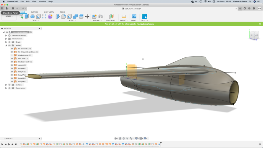
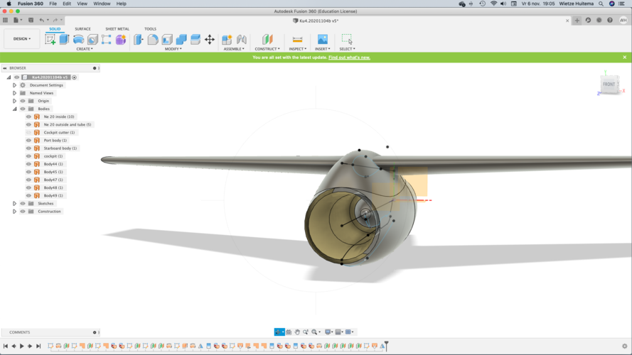
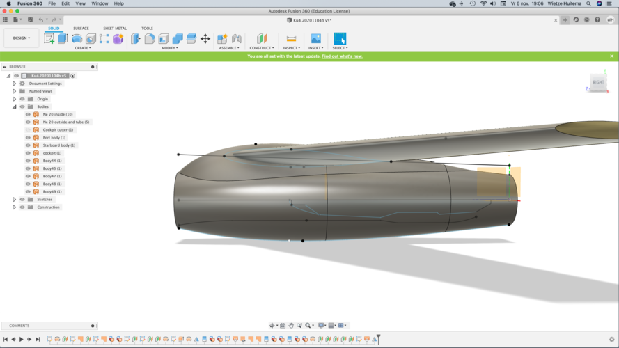
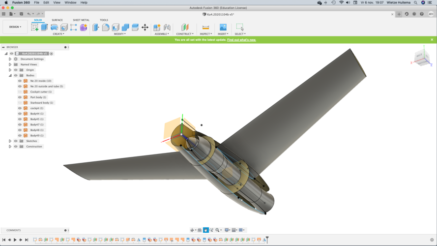
I'm trying to build a computer model based on the views Justo provided in this thread.
The wings are a quick insert and not according to plan yet.

The views are quite different from the plastic models I found on the internet. Are there original plans? Are the views from Justo based on them?

Regards,

Wietze


1604685859644.png

1604685952035.png
1604685983235.png
1604686047878.png
 

Similar threads

Please donate to support the forum.

Back
Top Bottom