shockonlip
ACCESS: Top Secret
- Joined
- 29 January 2008
- Messages
- 605
- Reaction score
- 57
These photos and information were provided through the courtesy of
Sannu Molder who has been an important contributor to scramjet engine research
going back to the 1960s, and is still involved, to this day.
Sannu was also heavily involved in the development of the scramjet
powered HARP (High Altitude Research Program) vehicles (called
Martlet IIs) you will be seeing photos of here. Of all the vehicles
launched by Project HARP the scramjet powered vehicles were pretty rare.
I have encountered only one reference to these scramjet Martlets before, namely:
HYPERSONIC AIRBREATHING PROPULSION: EVOLUTION AD OPPORTUNITIES (AGARD CP-428)
by P. J. Waltrup; The Johns Hopkins University Applied Physics Laboratory
In fact the above ramjet/scramjet history called Sannu Molder's efforts
here: "these are the only reported attempts to actually flight test a
scramjet" at the time of publication of this JHAPL paper. I think this
makes them the first scramjets ever flown.
Sannu Molder and his associates developed these vehicles in the 1960's !
And if you look at the inlet technology, it is the same basic inward turning
technology being used today. These inlets were based on Busemann's theoretical
work published in the 1940s.
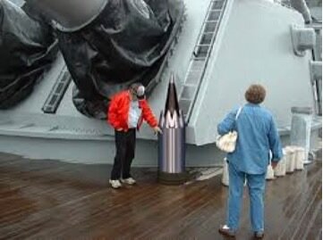
Project HARP, as it was installed down in the Barbados, used
a standard US Navy 16" MK I battleship gun, smooth-bored initially
to 16.4 inches and then enlarged to 16.7 inches when extended
to its full final length.
The photos follow:
001 - A diagram of a inward turning scramjet inlet module.
The first photo shows the schematic of one module. Point "A" at
the tip is at the tip of the vehicle centerline. Each scramjet
module (of which there are 4) is joined at point "A".
Another important point to look at is the triangular exit of
the inlet module labeled "M3". I will point out these locations
in the photos of the actual inlets.
002 - Here is a photo of an actual Martlet II scramjet vehicle
modular inlet. We are looking down at one module. Point "A" of this
module is at the very tip at the top. To the right of the module
we are looking at, you can make out another module turned 90 deg
to the right. Likewise on the left of the module seen in the picture
is another module turned 90 deg to the left. And behind the module
in the photo, turned 180 deg from the module in the photo is yet
another module (you can't see it because it is directly behind the
one in the photo). The point "A"s of each of these modules are joined
at the very tip. So if you looked down at the inlet you'd see
4 modules, each taking 90 degrees of the vehicles circumference.
003 - Now we look at the end of the inlet. Remember the triangular exit
labelled "M3"? You can see each of the 4 scramjet modules has a
triangular exit area. Each of these exit areas goes to its own supersonic
cumbustor in the main fuselage of the scramjet attached below this inlet.
In the center are the screw threads which attach the inlet to the fuselage
of the scramjet vehicle. Also this center area is where the fuel tank
of the scramjet vehicle is. It is also the main load carrying member
of the huge G-load of cannon launch 20,000-50,000 G's !!
The fuel used is Triethyl Aluminum (TEA - (C2H5)3 Al). TEA is highly
reactive (ignites with air at room temp. and reacts explosively
with water). Such a fuel is more sure to burn in marginal ignition
conditions. The fuel injectors for each of the four inlet modules are
inside the inlet component of the scramjet vehicle and can't be seen.
004 - At the end of the scramjet is the nozzle and fin area. As you look
at the end of the actual nozzle, you see the circular area where
the main load carrying fuel tank is. The pusher plate, which attaches
to the end of the scramjet for gun launch pushes against the end of
the fuel tank here when the gun fires.


