Lionel Haworth went on to say:
"It was natural that we chose for the compressor of the RB.53 a two-stage centrifugal type, the type which in fact we had used on later Merlin and Griffon engines. This was drawing on our previous piston engine experience; we thought that we knew something about reduction gearing since the Merlin and Griffon featured these components, but we had not attempted anything with such a large ratio as .106. The piston engine had a much smaller reduction gear ratio of .442. Having decided on the main construction of the engine, some calculations were made to determine the approximate size of the engine. In order to have 1000 hp at the propeller it was necessary to have a turbine that developed about 3000 hp driving a compressor that absorbed about 2000 hp.Thus the rough basic dimensions were arrived at. With the compressor we were hoping to use our latest knowledge and maybe a little beyond. With the turbine we decided to go beyond our jet experience and have a two-stage turbine. This engine was the first aero engine in the world to feature 2 stages in the turbine.
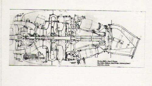
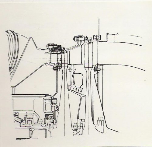
The engine was then sketched out to produce a design scheme with the main components worked up in enough detail for estimates of weight to be made. The project layout or scheme is then turned into a detail design and a General Arrangement generated."

The RB 53 design project started on or around 25th April 1945 and it took 57,048 man hours over a period of 63 weeks to complete the initial design. Detail design of component parts began 12th June 1946 and took another 29,195 man hours over the next 54 weeks. First detail drawings were issued to the shops on 1st Nov 1945 and the first engine was built and ready for test by July 10th 1946.
Haworth continues:
"As soon as the engine was completely assembled, it was put on a weighing machine. Imagine how we felt when instead of showing the predicted 700 lb, the scales showed over 1100 lb! But this was not the worst blow we suffered during that second week of July, 1946; a few days later the engine was wheeled from the shops to the test bed and the anxiety as to whether it would in fact run was completely overshadowed by an inquest in the design office on the weight analysis. The engine,however, did run even under its own power, but when the next day it was decided to open up to full power we were completely stunned by the news - our 1000hp engine could only achieve a little over 600 hp. It, however, was decided to persevere with the 'heavy' engine and within a matter of a month or so it had completed a 50 hr endurance test. We were now faced with the task of finding the power and reducing the weight and these two design problems occupied us for the rest of 1946 and well into 1947.
Every piece of the engine was carefully examined to see were metal sections could be reduced or avoided all together to save weight. Magnesium was used extensively for castings instead of aluminium, and by a process of pruning every ounce of weight on desin and making certain castings were manufactured to drawing thickness (almost 100 lb of weight was put on through overthick castings) we managed to achieve a saving of some 350 lb.
The loss in power output was not really surprising on closer examination, for instead of the turbine developing 3000 hp it only achieved about 2800 hp, and instead of the compressor requiring 2000 hp it was taking over 2200 hp leaving only 600 hp for the propeller.
Another version of the RB 53 was produced which gave about 900 hp and weighed 800 lb. This engine was developed up to 1000 hp and in Aug 1947 the first 150 hr Type Test was attempted. It was not until Dec 1948 that a clear run throught the 150 hr test schedule was achieved, at a power of 1045 hp. In April 1949 a 500 hr endurance test was completed at this rating."
An aside: At some point during the War Haworth had visited Dr. R. W. Bailey at MetroVick, Manchester and had been shown a disc in the laboratory being subjected to steep radial thermal gradients by alternately heating and cooling the rim. Dr Bailey expalined he was simulating the thermal stresses that occur transiently in an engine, saying he planned to find out if the metal would attain what he called a 'cyclic state'. He further said he believed the rim hoop stress alternated between tensile and comprssion in excess of the material yield.
Haworth decided that such punishment would fail the disc and went away to find a design solution to the problem.
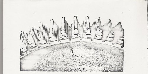
The 4th attachment below shows a crack at the bottom of the blade root slot of a Derwent engine. 13 Derwent discs failed in service from cracks like this (typical across the industry at the time). While these failures were occuring Haworth was having a design solutiion fitted to the improved RB 53 being developed. This was the extended root blade.
Back to Haworth:
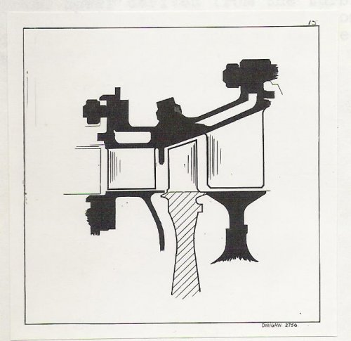
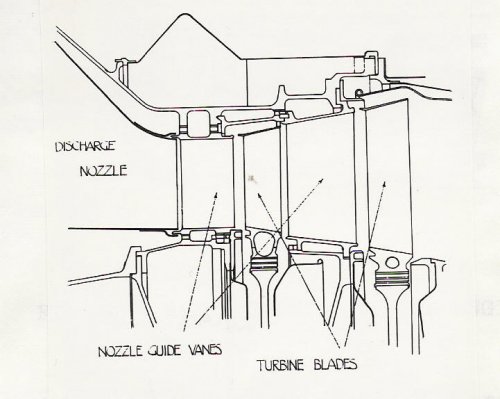
" The improved power derived from the turbine by blocking up the leaks under the NGVs prompted some thought to be put into the idea of blocking up the leaks over the top of the turbine blade.
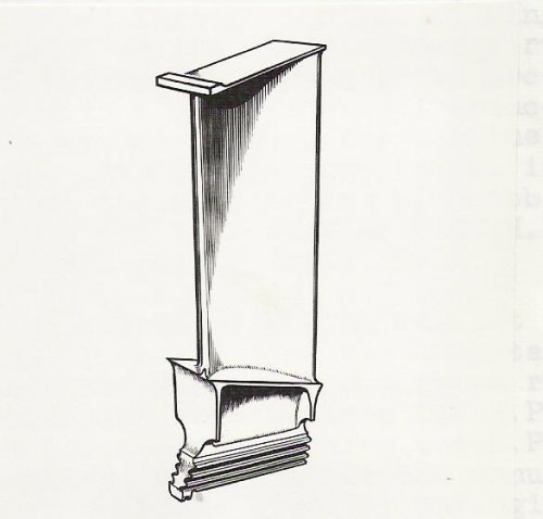
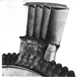
This was eventually achieved by designing a turbine blade with a shroud on it and to seal off the hot gas on the front edge of the blade by a very narrow land running against a face with as small a clearance as possible. Hence this engine was the first aero engine to have shrouded blades and, incidentally, long roots. Obtaining the correct clearance was very much more difficult to calculate and we resorted to trial and error, observing the stae of the shroud upper surface through holes in the casing. We adjusted the running clearances until we only had a slight rub.
The improved turbine design gave a substantial increase in efficiency and by Oct 1948 we were able to complete a type test at 1100 hp and an sfc of .867.
 

Attachments

  • RR-RB 53 Dart- early design scheme.jpg
    RR-RB 53 Dart- early design scheme.jpg
    51 KB · Views: 102
  • RR-RB 53 Dart- shrouded Turbine Blsde with extended root.jpg
    RR-RB 53 Dart- shrouded Turbine Blsde with extended root.jpg
    27.1 KB · Views: 62
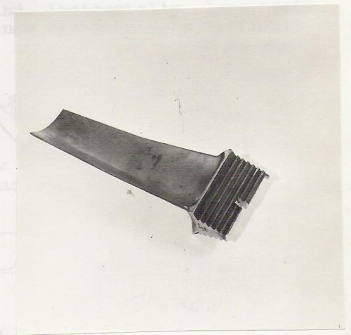
  • RR-RB 53 Dart- unshrouded Turbine Blsde.jpg
    RR-RB 53 Dart- unshrouded Turbine Blsde.jpg
    32.3 KB · Views: 51
  • RR-RB 37 Derwent-thermal fatigue crack Aust steel T disc.jpg
    RR-RB 37 Derwent-thermal fatigue crack Aust steel T disc.jpg
    266.6 KB · Views: 51
  • RR-RB 53 Dart- early des scheme T Blsde and NGV.jpg
    RR-RB 53 Dart- early des scheme T Blsde and NGV.jpg
    54.8 KB · Views: 52
  • RR-RB 53 Dart- early illustration T Blsde and NGV.jpg
    RR-RB 53 Dart- early illustration T Blsde and NGV.jpg
    47.1 KB · Views: 60
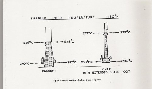
The benefit of the long root blade that Haworth had fitted to the Dart was that, not only did the thermal cyclic stresses reduce, the disc rim temperature profile was so much lower that ferritic steels could be used instead of austenitic steels. The Americans were very slow to adopt the innovation choosing instead to pour money into the manufacture of austenitic and nickel based discs. Incidentally the rim temperatures on the Concorde engine exceeded the limits for ferritic materials and we had to use American Waspalloy material for any practicable design.
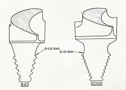
Another benefit of the long root blade is that a large radius at the top of the firtree greatly reduces the stress concentration at this point eliminating frequent failures that were happening in that area on conventional blades.
 

Attachments

  • RR-RB 37 and 50 turbine disc temperatures compared.jpg
    RR-RB 37 and 50 turbine disc temperatures compared.jpg
    159.1 KB · Views: 54
  • RR-RB53 Dart-avoidance of piling up stress concentrations.jpg
    RR-RB53 Dart-avoidance of piling up stress concentrations.jpg
    117.2 KB · Views: 62
Back to Howarth:
" At this (1100hp) power the shrouded turbine was not fully exploited and a further redesign of the turbine was undertaken as a result of research undertakenon a turbine rig. It was decided to redistribute the work between HP and LP stages, reducing the LP and increasing the HP. This was achieved by altering the annulus and increasing the HP blade speed slightly by arranging the HP blades at a slightly greater effective radius. This configuration gave an equal 'hade' at (inner and outer annulus diameter) and by pressurising the outside of the NGVs with high-pressure air thus stopping any internal gas leakage. The result was an increase in turbine efficiency from 80 to 86% at the altitude cruise condition.
Several refinements were made to the compressors, in particular, aerofoil type diffusers were introduced which raised compressor efficiency from about 74% to 78%. At the same time the mass flow of the engine was increased from 18 to 20.8 lb/sec, of which 20.1 went through the turbine. This engine gave 1400 hp and by Sept 1950 a 150 hr TT was completed at 1400 hp and an sfc of .836. This engine became known as the RDa 3 and was put into production; the first one coming off the production line in April 1952."
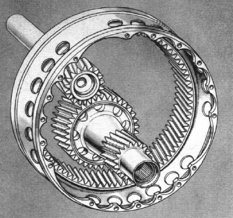
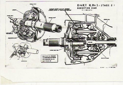
It also had the Helical Reduction Gearbox driving the propeller. Fretting problems in the gearbox had once again highlighted the problem of spur gears.
All these comments date from around April 1954 and thoughts on how the Dart might be further developed were included.Testing had shown that further aerodynamic refinement enabled the HP NGV numbers to be reduced from 98 to 84 - worth another 1% on turbine effeciency. A second seal was provided on the HP Turbine blade shroud and the combustion chamber pressure loss was reduced to increase their efficiency... all this added up to a 150 hp increase with a slight sfc reduction. This RDa.6 engine went into production at 1550 hp and was fitted to a Viscount with an AUW of around 60,000lb and an improved cruising speed (plus 10-15 kts). It was also the engine used to power the Fokker Friendship. The engine first entered service in April 1956
Further research on an even more powerful engine required more radical change.
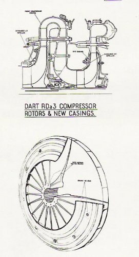
One idea that went to test was the shrouded impeller. This enabled the air to move through the impeller without scrubbing along a staionary wall, reducing turbulence. Such an impeller was then very expensive to machine. There were also mechanical integrity issues that made practical use of such a design problematic.
Also developed was a three stage turbine which with its improved work distribution resulted in a turbine that not only gave 90% efficiency at sea level, it also delivered a similar figure at cruise conditions, unlike the 2-stage design.
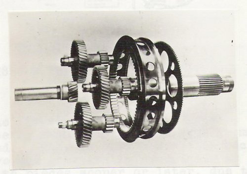
The reduction gearbox was also redesigned for the RDa 6 onwards.... an all-helical gear train ....to accommodate further increases in power. The first redesign, when the helical gears were introduced on the high-speed train, cured the dangerous resonance inputs that were causing problems but still left a great deal of vibration that had to be coped with. In the words of R. J. Shire, an engineer on the Dart project:
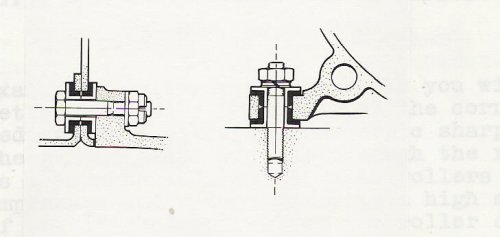
"On our Dart engine the improvement [after fitting the helical low-speed gear train) was quite remarkable, so much so that we felt it would be worthwhile to make the low-speed train also helical. The problem here was to obtain a machine which did not exist, to grind an internal helical annulus. We paid visits to the Birmingham Gear Grinding Company and it was quite a major undertaking to persuade them to design and perfect a machine to grind an internal helical annulus to the degree of accuracy we were demanding. However years of work went into this job and now [1954] we have recently had our first engine on the test bed featuring the helical teeth on the low-speed train. From first observations it appears very encouraging, the engine being much smoother and free from vibration around the front end. This is comforting because over the years we have had practically everything at the front of the engine drop to pieces sooner or later, due to the severity of vibration; so much so that we were obliged to mount on specially designed very small shock absorbers, the front cowling ring, the oil cooler, the propeller spinner extension and various accessories like the torquemeter pressure transmitter.
 

Attachments

  • RR-RB 53- helical low speed gear train.jpg
    RR-RB 53- helical low speed gear train.jpg
    184.4 KB · Views: 56
  • RR-RB 53 Dart- anti-vibration mountings.jpg
    RR-RB 53 Dart- anti-vibration mountings.jpg
    26.4 KB · Views: 60
  • RR-RB 53- cutaway of RDa.3 stage 2 strengthened helical red gearbox.jpg
    RR-RB 53- cutaway of RDa.3 stage 2 strengthened helical red gearbox.jpg
    67.9 KB · Views: 68
  • RR-RB 53 Dart- shrouded rotor and casing.jpg
    RR-RB 53 Dart- shrouded rotor and casing.jpg
    38.9 KB · Views: 65
  • RR-RB 53- exploded photo of RDa.3 helical prop red gearbox.jpg
    RR-RB 53- exploded photo of RDa.3 helical prop red gearbox.jpg
    42.3 KB · Views: 69
  • RR-RB 53 Dart- later des scheme T Blade and NGV.jpg
    RR-RB 53 Dart- later des scheme T Blade and NGV.jpg
    53.9 KB · Views: 68
Could you in a future attic dig look for Conway conception? This my understanding of that:

- 23/12/42: English Electric Co (equity-controlled until 1949 by Westinghouse, USA) bought D.Napier & Son, whose design competence lay largely in its part-time consultant, Halford, who concurrently worked on schemes for DH;

- 1/2/44: DH Engine Co. was spun off: MD, F.Halford, severed his Napier function;

- 28/4/44: Power Jets Ltd was nationalised, to be confined to research/laboratory (and redefined 1/7/46 as NGTE). MAP diffused PJ Intellectual Property across the established industry, through the Gas Turbine Collaboration Committee. Halford had taken H.1-6 to DH; Napier had licenced Jumo 4 in 1934 before charging disastrously into Halford's Sabre. Now their sole innovations were H.7 (unwanted at DH, becoming Oryx gas generator), and Junkers-inspired compound/diesel E.125 (to be Nomad I). From W.2/700 and LR.1 turbofans, Napier schemed E.132, taken up by EE (naturally) and by Short in May,1947 bids to the Medium Bomber. EE was quickly rejected; Short was awarded low-risk, insurance Sperrin, 11/11/47, with low-risk AJ.65;

- 1/48: within MoS-managed industry rationalisation, MetroVick exited aero-engines, and George Nelson sold E.132 to RR. Hives let his Chief Scientist, Griffith, play with it while down-to-earth folk did the practical things you are reporting. But he brought it on, such that MoS, 10/51, ordered 17 Valiant B.2, RB.80 intended to displace Avon asap.

Gunston Encyclopaedia of Aero-Engines,1986,P.145 (un)credits AAG: "Following prolonged Griffith studies, Govt. funding was obtained in 1952 for...RB.80 Conway". Did it, in fact, have pedigree back to Griffith, or Napier, or Power Jets?
 
Alertkin... the bypass engine that became the Conway was a pure RR affair... we can deal with this shortly! E.131 to E.134 and E. 137 were jet engine projects that only got as far as layouts in the Design Office.
P.S. tea chests are cheap filing systems but are not good at facilitating retrieval.
 
The (sole?) published source for this is the HP Putnam, P.497: (About Spring,1948) "RR undertook further development of the Napier-designed E.132...redesigned it (at Barlic) as RB.80/1 and later it was named Conway."

The magic of the name included an institutional aversion to acknowledging Mercedes in Eagle, Curtiss-Wright D.12 in PV.12, Sapphire compressor in fixed Avon 100, (Chrysler block in 1950s' Silver cars), or any RAE/NGTE value in, well, anything. Compare Bulman's account of Govt. infusion of money and RAE wit to get Merlin through type test, with Chairman's 1936 assertions to Ministers that RR "owned" it and would not permit (the word for second-sourcing then was) sub-contracting. Vickers (Aviation) took the same position on their "PV" Spitfire. Both were balderdash: A.M had paid for darn nearly everything upfront and the rest in later overhead. Yet, frustrated at foot-dragging, Air Minister Kingsley Wood nominated the design parent to handle volume production at his factories, Crewe & Glasgow, whereas Bristol aided entry of the auto industry. The auto team co-ordinated by Austin, and later Ford/UK and Packard on Merlin, gave short shrift to the notion that fabrication of aero engines was magical beyond autonauts' wit.

Not until the generation raised by Hives was cleared out after 1971 did "collaboration" enter Directors' lexicon (i.e joint design, as opposed to production licencing). That's why in 1959 Medway could not be taken into Allison for Boeing 727, or teamed with ASM to go into TSR.2, so then Concorde.

If C.H.Barnes' Putnam is right, then Conway emerged from a combination of competitor and scientist - both offside to the Derby insiders. That would answer Qs, such as here, on modesty of R&D effort into RB.80, causing the by-pass first mover so rapidly to be beaten by upstart Pratt. Why else re-invent it, as Medway?
 
Alertkin,
I have the photos of the Mercedes in the shop at Nightingale Road, Derby in 1914... and the new crankshaft we made for it as the original was not good enough! The basic concept was useful to Rolls but it was a much improved engine that superficilly looked like the Mercedes that emerged... but that is a story for another time. The highly beneficial collaboration between Ford in the UK and RR Deby is a story that shows how Hives was a willing leader in setting that up... the shadow factory at Trafford... where the Temple to retail now sits... came on stream extremely quickly... another story..Note nearly 100 Ford personnel were at Derby to understand and prepare drawings for the mass-produced Merlin, as distinct from the craft-produced Derby ones, and the batch produced Crewe ones.. ideal for reacting to German improvements in their engines and then rolling out in larger numbers. Hopefully this story will get published under the working title of 'Oliver's Merlins' soon...
So my conversations with Jim Boal and others about working with P&W in the 40s does not necessarily support the general view that has grown up over the years.
The Conway story started out in Oct 1946 with the start of the BJ 45 and as power requirements increased so iterations (Oct 47, Apr 48) took place around the basic BJ45 configuration. The actual RB.80 designation was a later development... but many pundits assume that because the B stands for Barnoldswick then that is where the design was done. In fact the RB became the general Rolls prefix when design office finally moved to Derby mid-1948 and the Barlic design project register continued to be used. The Avon had started at Derby and then transferred to Barlic only in 1947 to be moved back... due to the appalling performance and the need to get all of Derby's knowledge into solving its problems. The final iteration of the BJ 45 bypass principle was Oct 1948 when it was given the designation RB.80.
The bypass concept originated in RR when Griffith continued to think about jet propulsion he started at Farnborough (as we have discussed elsewhere in the thread)
Griffith recounted his bypass activities:
"The first RR scheme exhibiting the bypass principle was CT56, which was done by DE [Don Eyre] in 1940. This was, of course, a multi-spool type. My own first thoughts on the subject were late in 1939, but as DE had not joined me then. ...In 1946, came a two-spool scheme whose compressors were cooked up from the Avon and Tweed compressors. A paper based on this was submitted to the TJR Sub-Committee of the ARC about November or December 1946."

...tbc
 
An aside... as we can see (when completed) above the effort on Dart, and other engines, is about performance enhancement, mechanical integrity and life (tbo) enhancement... This document issued 2008 shows level of support for an 'old' engine.
 
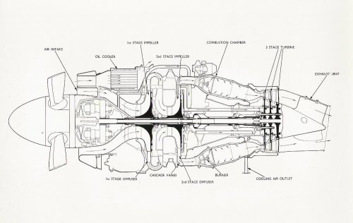
Two other major changes were introduced as the Dart was upgraded form RDa.3 to 6 to 7. The method of attaching the turbine discs to the shaft as the number of turbine discs went from 2 to 3; the transfer of torque from the turbines to the compressor and the propeller gearbox was changed from a single shaft to concentric shafts, one driving the compressor, one driving the gearbox. Both were introduced to improve the reliability of the engine and to ensure that in the event of failure of either an impeller or gearbox did not lead to a turbine overspeed.
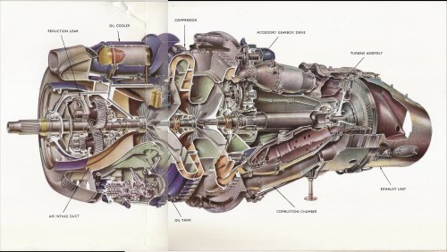
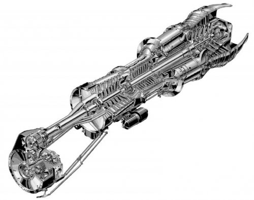
The cutaway of the Dart with 2-stage turbine shows the method of location of the two discs via radial dogs midway up between the discs. The cutaway with the 3-stage turbine shows how the discs use a method similar to the Tyne with through bolts; 5 bolts are used to assemble the first two stages and the third stage is attached by a further 5 bolts, concentric and, spaced between the first set, going through all three discs.The section shows how a second shaft arranged concentric with the normal main driveshaft is arranged... it goes on to drive the main gearbox, but as it is splined to the mainshft acts as one.

In 1957 new revisions to airworthiness requirements for turbine-powered aircraft specified the minimum aircraft climb gradients in the event of an engine failure and which required that the effect ofbient am temperature on engine performance be taken into account. On the Friendship, for instance this imposed severe limitations to take-off weight under hot day conditions.
The most severe condition was the 'final segement' singl-engined climb gradient when the remaining engine operated at max continuous power. On the RDa6 the original max cont power reduced with increasing ambient temp and so the Friendship had severe weight restrictions. To alleviate this RR worked had to increase the max cont. rating. Eventually the Mk 511-7E engine version delivered 1600 shp upto 25 deg C ambient. Max continuous was a higher power than T/O without detriment to the engine as it is only used in an emergency. In spite of these increases in power and the short stage lengths flown by the Friendship, the RDa6 had a tbo of 4000hrs and the RDa7 3600 hrs in Jan 1964. The military versions operated at 2470 hp (RDa8) in the Argosy with a life of 1200 hrs. The RDa 7 has a higher mass flow than previous engines (22 lb/sec up 2lb/sec on RDa6) with a second stage impeller 0.4 in greater in diameter at 17.6 in, rotating 500 rpm faster at 15,000 rpm.
Turbine blades now sported 3 seals, 2 on top and the third forward facing
 

Attachments

  • Dart turbine blade shroud with 3 seal strips.jpg
    Dart turbine blade shroud with 3 seal strips.jpg
    11.5 KB · Views: 2,066
  • RR-RB 53 Dart- engine x-section 3 stage turbine.jpg
    RR-RB 53 Dart- engine x-section 3 stage turbine.jpg
    203.3 KB · Views: 99
  • RR-RB 53 Dart- Cutaway Dwg-3 stage turbine.jpg
    RR-RB 53 Dart- Cutaway Dwg-3 stage turbine.jpg
    510.6 KB · Views: 96
  • RR-RB 53 Dart- Cutaway Dwg-2 stage turbine.jpg
    RR-RB 53 Dart- Cutaway Dwg-2 stage turbine.jpg
    450.4 KB · Views: 94
Meanwhile over at Allison they were developing a higher powered turboprop that had a twin-spool configuratio. With a seal level static T/O power of 6,102 shp +996 lbt =6,500 eshp, it had a 6-stage lp comp'r with tapered O/Diameter and 8-stage hp comp'r with cylindrical outer casing, 10 flame tubes in can annular format, 1 hpturbine and 3 lpturbines driving compressor and propeller gearbox. The Allison 550 T61 engine was developed from 1955 to '59. Nov 30th 1959 saw the end of USAF funding which had totalled $35 million. 4 engines were on test and one was to go in a YC-130B in No 3 position but never flew before programme ended.
 

Attachments

  • Allison T61-twin spool-cutaway.jpg
    Allison T61-twin spool-cutaway.jpg
    57.8 KB · Views: 93
A couple of 'secret projects' that the Dart enabled.

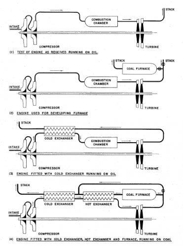
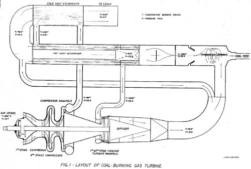
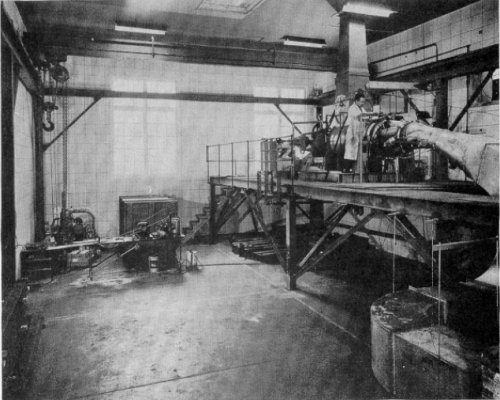
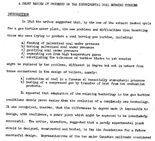
D L Mordell initiated a coal burning gas turbine project at Canada's McGill University and wrote a review (1955) after operating the plant for several hundred hours.
A second application for Darts was in static and rotating rigs for the Rotodyne project
...and in a rerun of the 'restaurant at the end of the universe' here is the third example in the couple... at Pyestock .. a rig for circulation control.
 

Attachments

  • Coal burning gas turbine-lalternate test arrangements.jpg
    Coal burning gas turbine-lalternate test arrangements.jpg
    103 KB · Views: 523
  • Coal burning gas turbine-layout.jpg
    Coal burning gas turbine-layout.jpg
    186.2 KB · Views: 513
  • coal burning dart test bed-McGill.jpg
    coal burning dart test bed-McGill.jpg
    245.9 KB · Views: 518
  • coal burning dart test bed-McGill- a review intro.jpg
    coal burning dart test bed-McGill- a review intro.jpg
    198.7 KB · Views: 530
We have talked in a different thread about the RB 162 engine, design of the engine started in the Spring of 1959 with a first run in 1965. Early in the synthesis of the design it was called on as the basis for a solution to the requirements growth of the Rotodyne that even swapping from Eland to Tyne could not cope with.
In ‘Requiem for the Rotodyne Flight 9th August 1962, the article includes this extract about the powerplant for the civil version:
Powerplant The tip-driven rotor is fundamental to the concept. Especially with rotary-wing aircraft of the largest sizes, it is lighter than a geared drive to the hub; but it also has a higher fuel consumption, and so in the Rotodyne was used only for VTOL.
Many types of tip drive are possible. The simplest employ tipmounted rockets, ramjets or pulsejets, but these suffer from inordinate specific consumption. Pressure-jet units may be employed either with or without combustion at the tip of the blade. Without combustion the required duct area makes the rotor aerodynamically unsuited to high-speed operation, and this type of system is likely to be applied only to cranes and other slow-flying craft. With tip combustion, rotor horsepower for a given flow through the blade is enormously increased, and there seems no reason to doubt that the Rotodyne rotor was the most efficient that could possibly be devised.
Like most aeronautical design problems, a tip-driven rotor is the end-product of a series of compromises. The blade profile must be the optimum aerodynamically; the duct must be accommodated wholly within this profile; the e.g. must be located at not more than 25 per cent chord; for peak efficiency, pressure ratio must be correctly chosen; tip speed is limited by Mach number; ideally, jet velocity should be not greater than twice the rotor tip speed, but this would take the size of the duct outside the blade profile; each pressure-jet unit becomes pure drag and weight in cruising flight; noise from such a rotor may be severe, and of an unfamiliar character; and means must be found to provide for engine-out operation.
Complication is introduced by the need to provide for engine out operation. If two sources of compressed air were connected to a single pipe serving all four blades, loss of either source would result in unacceptable loss in rotor horsepower (much more than 50 per cent). The Rotodyne rotor operated as two opposite pairs of blades, each served by one of the sources of compressed air.
Termination of the supply from either source was automatically countered by increasing the fuel flow to the remaining pair of pressure-jet units, thus restricting the drop in rotor horsepower to below 13 per cent. At maximum weight, this enabled a satisfactory VTOL landing to be carried out. But this could be achieved only by designing the pressure-jet units for severe combustion conditions.
In the Rotodyne Y all power was provided by a pair of Napier Eland engines, each rated at 2,800 s.h.p., driving 13ft Dowty Rotol propellers. The single-shaft Eland also had a gear-tooth coupling at the rear driving an hydraulic clutch and auxiliary compressor.
The hydraulic clutch was a compact unit based on Sinclair principles, and by being either filled with oil or drained provided either a firm drive with very little slip or, with infinite variation, progressively less drive down to zero. The auxiliary compressor could absorb up to 80 per cent of engine power and deliver to its pair of blades a mass flow of 19.51b/sec of air at a gauge pressure of 471b/ sq in (the uprated E.151A could deliver up to 22.71b/sec).
But natural growth of the project caused the shaft-power requirement to rise beyond 4,000 h.p., which Napier regarded as out of their reach. During 1960 it became obvious that a switch would have to be made to the Rolls-Royce Tyne, although even this 60
per cent increase in power barely matched the increase in the requirements of BEA and the Services. Under hot and high conditions, the 5,250 s.h.p. Tyne 550 could only just provide the power required without any stretch in the development schedule or reduction in engine life.
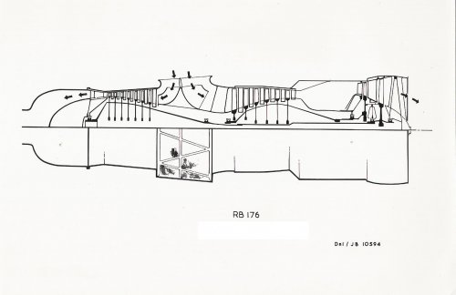
Eventually Rolls-Royce suggested separate air-producing engines. Their solution was to instal in the rear of each nacelle an RB.176. This would have consisted of a lightweight gas turbine with a front extension shaft driving an auxiliary compressor. From the engineering viewpoint this arrangement was in some respects preferable to the previous installation with long shafting and hydraulic couplings. Total powerplant weight would have been about a ton heavier, but the use of separate propulsion and lift engines gave added flexibility under critical flight regimes, and also promised substantial gains in performance under hot and high or off-design conditions. In helicopter flight under the original scheme the Tynes would have been held at constant r.p.m. by the fuel governors to provide optimum propeller control, while air delivery to the rotor would have been controlled by opening or closing shutters in the auxiliary compressor intakes. In the final scheme the turboprops would have had separate controls, and the RB.176s would have been subject to coarse control from levers bearing the legend Rotor Power Control: Start-Idle-Takeoff. The pilot's collective-pitch twistgrip would have been coupled mechanically to the datum of the governor controlling lift-compressor r.p.m. and fuel-flow; this linkage could aiso be operated by the rotor speed governor. A pressure signal from the air supply would be combined with a fuel/air ratio demand to establish almost instantaneously the correct fuel flow to the tip jets.
Originally the Rotodyne pressure-jet unit consisted of a circular section flame tube, fed by three air pipes and a single fuel pipe,
faired within a streamlined nacelle and terminating in a simple propulsive nozzle. But the BEA Type Specification stipulated an initial climb at zero forward speed at maximum weight not less than 600ft/min with a sound pressure level 600ft from the rotor
axis not exceeding 96db. Ignoring the noise requirement for the moment, this meant that each of the two pairs of blades had to generate 3,850 h.p. with an airflow of 331b/sec and a fuel/air ratio of 0.04. The specific consumption was approximately 1.851b/rotor h.p./hr. It was a requirement that the aircraft should be able to hover at maximum weight with either engine inoperative and the other at 2.5minutes max contingency of 7,390 h.p. (with water/methanol). The remaining engine would feed only one pair of blades, and could provide a maximum airflow of 43lb/sec. Emergency power to the rotor was achieved by selecting maximum engine speed and water/methanol injection with the power levers, and twisting the collective-pitch twist-grip to the limit of its travel. This would allow the rotor speed governor to increase the fuel/air ratio to the two remaining units from 0.04 to the stoichiometric value of 0.065, to increase chamber temperature to 2,200-2,300'K, and raise the power developed by the pair of blades to approximately 6,500 rotor h.p. With RB.176 engines the required takeoff rotor power of 3,850 h.p. per half rotor was achieved using 431b/sec air mass flow and a fuel/air ratio of 0.02. The emergency power to the rotor was achieved partly by an increase in engine power without water/methanol injection to max contingency rating, but mainly by an increase of tip-jet combustion temperature corresponding to an increase in fuel/air ratio from 0.02 to 0.065. This variation of power input was obtained by manually removing a mechanical stop and twisting the collective-pitch twist-grip to the limit of its travel.
Noise from the rotor was severe, and the problem was rendered acute by the fact that it was of an unusual "chuffing" character.
Intensive work on the problem began in mid-1956, but the effort was accelerated owing to both the increase in rotor power and the stipulation of an agreed level for civil operation. In fact, the actual noise of an unsilenced unit at 600ft was approximately 113db. To achieve the 17db reduction demanded for civil operation would have necessitated a redesign of the pressure-jet into a two-dimensional form occupying the last 48in of each blade.
It was expected that the final unit would have nine circular flame tubes within a combustion chamber submerged within the blade profile. These liners would have been interconnected, with an igniter plug at each end of the chamber, and the exit nozzles would have been fabricated from molybdenum with a diffusion-deposited Si-Cr layer to prevent oxidation. This process required special furnaces which are only now becoming available in this country.
So the RB176 did not go ahead as the Rotodyne project was cancelled.
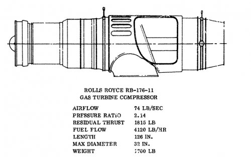
However a few years later there was a "STOL Tactical Aircraft Investigation", in the US, for a tactical STOL aircraft and the RB176 design was dusted off as a flap blowing powerplant... as the RB176-11, which was not selected for the later design studies.
We can compare the layout of the power unit of RB176 with the RB162 as it emerged here.
 

Attachments

  • RR-RB 176-x-section.jpg
    RR-RB 176-x-section.jpg
    123.2 KB · Views: 496
  • RR-RB 176-11 and details.jpg
    RR-RB 176-11 and details.jpg
    151.5 KB · Views: 98
Returning to the Derby bypass engine story....
In 1947 Derby were looking at straight jet and bypass solutions for the next generation combat engine to replace the Merlin in the factories. Hives did not necessarily see the future in turboprops; they had all sorts of problems when it came to handling over the aircraft performance envelope... especially when things were going wrong. A great deal of effort in the last 15-20 years had gone into maximising (horse) power per unit frontal area in order to power Spitfires, etc, and Hives could so no reason why this was not still important- especially for combat aircraft. Don Eyre produced a drawing to make the point that axials were the way ahead and Hives was right behind the people who believed this to be true.
On 29th August 1947 the Derby Weight Office issued a report that compared 2 versions of the BJ45 with the AJ45 and AJ65; the difference between versions is that version A incorporated Magnesium where possible, whilst version B had Aluminium but no Magnesium.

Engine BJ45 AJ45 AJ65
Ver A Ver B

Net dry weight lb 1536 1612 1800 1950
Spec wt lb/lbt sls 0.325 0.341 0.400 0.300
Frontal Area wt/ft*ft 235 248 300 184

The report states that the BJ45 is lighter than the AJ45 as the HP compressor spool and combustion equipment is smaller due to the HP system dealing with only part of the total airflow e.g. the AJ45 combustion equipment weighs in at 180 lb whereas the BJ45 weighs only 120 lb. The bypass duct made from 18 SWG sheet dural with stiffeners and expansion joint weighs 30 lb.
A later report dated 30th Oct 1947, the concept had been reworked to deliver a bypass engine with a T/O thrust of 7,500 lb; naturally this was called the BJ75
....tbc
 

Attachments

  • axial vs centrifugal- DE sketch.jpg
    axial vs centrifugal- DE sketch.jpg
    91.2 KB · Views: 84
Napier... oh Napier! It has a strange history of producing aero engines that wow and then not devoting enough energy to kepp wowing its operators. The first really succesful in-house design was the Napier Lion which was a great engine just after the First World War... designed by A J Rowledge, who then fell out with Montague Napier over the failure of the post-WW1 car which was a commercial failure. He left and joined RR, who benefitted greatly from having a man of calibre to help a sick Henry Royce. The success of the Lion kept them in business until the mid 20s with minor variations and Ministry funded versions... but there was no really aggressive development as the production engineers did not want to change anything and they were listened to by the board! Fell aked them to do a rival to the V-12 Curtiss Schneider engine but they declined so he went to Rolls-Royce who were suffering from a fall in car orders in the depression and Royce grabbed the opportunity to get back in aviation with a modern engine... this was the Kestrel... enlarged as the Buzzard... which was the basis of the Schneider winning R engine, and ttaught RR how to do rapid development under extreme pressur... useful less than ten years later in WW2 with first the Merlin then Griffon. In the meantime Napier realised that they needed to do something to survive! Montague's idea for an air-cooled V12 developed instead of the liquid-cooled engine Fell wanted (incidentally Fell's 2 draftsman drew out a scheme maximising the use of Lion components). They went to Halford, who was consulting deHavilland on small engines and so the Rapier and the Dagger were born. Unfortunately Halford had a habit of creating great schemes that needed a lot of development... but he was a bit blasé about telling people so Napier went into production without applying any rigour to development. Both engines had problems.... at the beginning of the War, on Hereford aircraft it would oil up and be difficult (=impossible) to start without taking out the lower sprk plugs and washing the out before refitting .. and don't hang about before opening the throttle! Halford had aslo designed the Sabre.. to be used in the next-generation fighter after the Hurricane, i.e. Typhoon... it turned out to have lousy altitude performance and in spite of work on superchargers was destined to be used in low-altitude roles only. The probem with, especially, sleeve valves, and other areas meant that Bristol were called in to sort this out and lack of urgency to tackle problems meant the Ministry asked English Electric to take them over. At one time no engines were going to Typhoons coming off the production line as all new engines were diverted to operational squadrons to keep those Typhoons in service in the air... it took till 1944 to sort this out, yet still the develoers kept coming up with even more highly stressed higher performing models. In desparation Derby were asked to do a Sabre replacement just in case... the Eagle II ....it was not a copy but what the advanced Sabre would look like as the Griffon did to the Merlin
So not surprisingly with that track record they were late into gas turbine development. In the 1930s they had taken a licence for the Junkers Jumo diesel aero engine and had built one or two as the Culverin...the became the basis of the Deltic rail and ship diesel engine series post WW2 and also accounts for why they were keen to do a Griffon replacement for such aircraft as the Shackleton... once again spreading their engine development resource too thinly.
The Ministry began to finance activity in gas turbines as the Sabre work reduced as the war ended... although the Sabre improved and its unscheduled outage reduced its life (tbo) remained short and so it occupied Napier till the last.... so it was late in 1945 when people like Herbert Sammons, H. Barlow and H. A. Penn were assigned to gas turbine development- as chief engineer, chief desiner and compressor expert respectively.
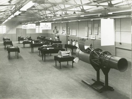
One of their first efforts was E127, soon known as Nymph, a turboprop of 525 eshp, again like Bristol given a small engine to look at. There is a 1946 picture, reproduced below, in the IMechE archive that is labelled Nymph. Looking at it with a close scrute reveals a sign above labelled Naiad; however the mockup? engine in the right of the picture looks too small to be a Naiad so maybe that is it. The design of the Naiad was certainly started early in the summer of 1946, first running in the summer of 1947.
 

Attachments

  • Napier Nymph-1946.jpg
    Napier Nymph-1946.jpg
    66.5 KB · Views: 96
The probem with, especially, sleeve valves, and other areas meant that Bristol were called in to sort this out ...

I'd been thinking of starting a topic about this. With hindsight, given all the problems, would it have been better to cancel the Sabre as soon as practicable, and merge Napier's resources with Bristol, and use them on Centaurus development/production?

cheers,
Robin.
 
We could do a WW2 what-if theme...but this is probably too wide as we could include almost anything!
 
You're right, a WWII topic would be too broad, so I'll start a new topic with my question form above, and another one I'd like to ask...

cheers,
Robin.
 
The Naiad was in the same power class as the Mamba and Dart but was never specified in the civil programme for the Brabazon type IIB short-medium range airliner (resulted in the Viscount with Dart and Apollo with Mamba). The coupled Naiad was funded as a military alternative to the Double Mamba. The Coupled Naiad was specified for the Blackburn Y.B.5 and Y.B.7 aircraft... the latter a rival to the Gannet. The development programme for the Blackburn was protracted and as Gannet/Dble Mamba was developing reasonably the funding was withdrawn for Coupled Naiad.
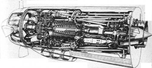
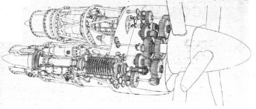
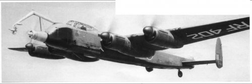
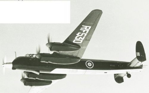
The original Naiad had a nacelle design the embraced a ducted intake in the spinner. Flight published a cutaway of the arrangement in 1951, first pic below, and it was estimated that the ram effect was worth 19% more than a standard intake but at the expense of weight and a propensity to icing (tests were conducted on Lincoln..as we have noted the techniques were useful to Bristol when the Proteus on Britannia ran into problems).
....tbc
 

Attachments

  • Napier Naiad cutaway with ducted spinner-Fl1951-0898.jpg
    Napier Naiad cutaway with ducted spinner-Fl1951-0898.jpg
    93.3 KB · Views: 114
  • Coupled Naiad cutaway-Flt1949-1578.jpg
    Coupled Naiad cutaway-Flt1949-1578.jpg
    69.3 KB · Views: 125
  • Napier Naiad icing setup in RF402.jpg
    Napier Naiad icing setup in RF402.jpg
    43.7 KB · Views: 113
  • Napier Naiad i in RF530.jpg
    Napier Naiad i in RF530.jpg
    21 KB · Views: 104
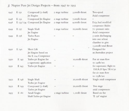
After WW2 The design office at Napier worked on various engine schemes for aircraft English Electric were designing in response to Ministry Specs...none of them resulted in a project progressing beyond the scheme, although work continued on component research that led to various Private Ventures funded by EE. Alan Vessey's book 'By Precision into Power' covers the bicentennial history of Napier from Napier's point of view. The appendix lists the E numbers from the drawing office register started by A J Rowledge when he was chief designer at the Acton Works... E1 is dated 1916 and led to the Lion broad W range of aero engines. AJR left in 1921 and joined RR.
I have scanned the Jet Design Projects. I have no reason to believe RR took on any of these schemes. The bypass for instance was well under way before Napier's first scheme... I think it is just that both were responding to same specs and RR had a good relationship with EE.... so similar thermodynamic calcs would lead to similar solutions... but not the same!
......tbc
 

Attachments

  • PintoP-Alan Vessey app pg 233.jpg
    PintoP-Alan Vessey app pg 233.jpg
    133.7 KB · Views: 99
tartle said:
Both engines had problems.... at the beginning of the War, on Hereford aircraft it would oil up and be difficult (=impossible) to start without taking out the lower sprk plugs and washing the out before refitting .. and don't hang about before opening the throttle!

From what i've read, the Daggers on Herefords also produced a whine that was intolerable after a very short time.
 
Let's go back to RR sampling Napier, as RB80 Conway. You discount this. My source, Putnam/HP,P.497 says in full "E.132 designed initially for 7,500lb...expected (soon) to reach 9,000 (about Spring,1948) RR undertook further development of (E.132) redesigned it at B'lick as RB.80/1." Just like you have been able to put right Bulman (on Sabre:Eagle), then mayhap CH Barnes is misled. Or maybe RR chose to broadcast its Napier origin to no-one other than AA.Griffith (who was given by-pass to occupy him, leaving proper folk to try to make AJ65 work).

What do we (think we) know? E.132 drew its compressor from Whittle W.2/700 and its by-pass (augmented; compound) scheme from Whittle L.R.1. In July,1947 MoS rejected the Short bid to (Medium Bomber, to be Victor/Vulcan) due to the unproven state of its engine (E.132). The EE bid was also rejected: it, naturally, had (EE) Napier E.132, but reason for deletion was to permit Petter to attend to A1. All this time we had neither money nor enemy. On 14/4/48 we acquired an enemy - Cabinet Tasking Chiefs to contain a Sov. thrust on N.Germany. MoS had organised 1/48 transfer of F.9 from MetroVick to ASM, to be Sapphire. What about me? might have been Hives reaction. Nothing from Brabazon. Hello! Vickers-Armstrongs won the third Medium 16/4/48, with AJ65. That was RR's first win since VJ Day. I have EE's Geo.Nelson selling E.132 to him there and then (where did I get that? Dunno now). So...

1. MoS paid for everything. PV R&D in UK aero-engine industry was, essentially, zero, ever. That's why Sapphire compressor later infused Avon, and why Fedden's sleeve-valves went to Napier, and...and...We owned it all.
2. What was ever actually unique, new, mine! And how long before it was sampled? And what do we mean when we say Whittle's this infused Napier's that? Paper schemes, bench/rig components; very little running of engines. What, exactly was passed to AA.Griffith to play with? Foo-foo valves and paper?
3. Let us not forget how modest were Aero's creative design/test resources: MoS considered EE/Preston's design team to be WEW.Petter. That's it.

Shall we assume that a (by-pass) pedigree flowed from Power Jets, through Napier, to RR, managed by MoS Gas Turbine Collaboration Committee, such that all Committee Members knew/could obtain access to all? So AA.Griffith could not have initiated Conway (as quickly, or as effectively) without Napier's riff. Barnes word "redesign" is too strong.
(F.Halford, onlie begetter of Sabre, designed H.1(Goblin)“from first principles,entirely independently of the Whittle concept” G.P.Bulman,An Account of Partnership,RRHT,2001,P.324. pace: H.1 “would not have been designed but for the stimulus and information provided by (W.1)” 2/10/47,Royal Commission on Awards to Inventors, awarding Sir FW £100K).
 
Alertkin:
I don't yet know what E.132 looked like but I do know that RB80/1 was a scheme that looks remarkably like the drawings done for BJ 45 one of a series of drawings that to quote Don Eyre "led to the RB80" and I could not imagine Don copying anything .. so I stick with my theme ... Conway was a RR engine... but that doesn't mean they did not see E132 layout. I saw P&W layout when I worked on RB178.. but that is all.. you would not say that one begat the other.
Also there is a book written by Michael Schrage called 'Serious Play' . In one section of the book he talks of 'Model Building: an Invitation to Interaction' :
“The value of prototypes resides less in the models themselves than in the interactions - the conversations, [/size]arguments, consultations, collaborations -- they invite. Prototypes force individuals and institutions to confront the [/size]tyranny of trade-offs. That confrontation, in turn, forces people to play seriously with the difficult choices they must [/size]ultimately make. The fundamental question isn't, What kinds of models, prototypes and simulations should we be [/size]building? but, What kind of interactions do we want to create? The latter question aims at the heart of strategic [/size]introspection. Consequently, the design focus - the value emphasis - must be on the quantity and quality of human [/size]interactions that modelling media can support. Who should be working together? What should they be talking [/size]about? Who should see the model next?”

In conversations with him a sketch or design scheme, the first draft of a proposal would count as models that change conversations.
So as Drawings flow about the industry they have an effect on the people who study them.
You are also right to point out that the Ministry paid for much of this work on a cost plus basis, owning the Intellectual Property that resulted. As you say this means information could be transferred between 'rivals' . The sleeve valve information passed to Napier was proprietary to Bristol and the Board of Directors had to be persuaded to pass it to Napier. They could have refused although that might have been a bad move politically.
The transfer of Sapphire compressor data to RR came about after AS were ordered to do it by the Ministry who, in this case, owned the IP.
 
PMN1 said:
From what i've read, the Daggers on Herefords also produced a whine that was intolerable after a very short time.

Sounds like my ex. (Badum-ching, I'm LO and I'll be here all week. Try the veal.)
 
Alertken....
You are right that there are connections that enabled the industry to sample and riff their way to some excellent engines.
This chart published by English Electric in a 1959 review of gas turbines written by W A Pennington shows the connections with the Whittle/RAE research centres... hope you like the colours!
 

Attachments

  • W A Pennington-EE-GT4Aircraft.jpg
    W A Pennington-EE-GT4Aircraft.jpg
    1.5 MB · Views: 149
Returning to the Tweed... a promising line of inquiry is the Saunders Roe archives.... if there are any. M J Brennan Assistant Chief Designer at SARO on the Princess recorded, in 1952, that" The determination of the best power unit whether piston, turboprop or turbojet poses the most fundamental problem of aircraft design and in truth is still subject to the skill and ingenuity of the designer concerned."

I did not realise that Princess did not come out of the Brabazon Committee's efforts, but from a commercial rivalry between Imperial Airways and Pan American.
In 1937 the two airlines were conducting flight surveys of the North Atlantic route with developed Empire Boats and Sikorsky 42s and later in 1939, when Pan Am had opened their first transatlantic service with Boeing 314s. The design staff at SARO were engaged on the study of a flying boat to meet the same requirements. A model, around 50% scale, was built and flown successfully- this was the SR37 with 4 Pobjoy engines. The war saw an end to this work but the data from the SR37 was used in the design and construction of the Shetland. In 1943 Brabazon Committee was determining post-war civil requirements but terms of reference did not cover flying boats. so separately a study was commissioned to provide the best spec for a N. Atlantic flying boat.
Saro's studies covered power arrangements using 6 and 8 Centaurus, and 6 RR Eagles.
Gas turbine's rapid evolution meant a new series of proposals with Clyde, Tweed, Python, Cobra and Proteus installations were worked up.
The final design proceeded in considerable detail with six coupled Tweed installations. But soon the Tweed was discontinued and the final choice of ten Proteus was made, with some hope that Brabazon would be able to build on the work to be undertaken by Bristol.... i.e. the Brabazon II.
So somewhere there may be papers on this original Princess arrangement.... more research continues!
 
An aside on the origins of the RB.80 Conway.
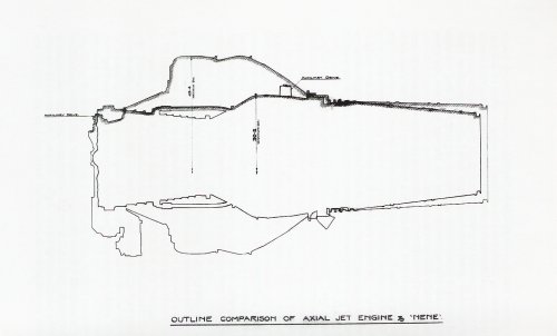
The E.132 of 1948 from Napier was the second compound or bypass engine to be designed; the first E.131 of 1947 had 2,000lb less thrust at 5,000 lbt.
Lovesey was working on his compound design in early 1945 and the first illustration made from the general arrangement was dated April 1945 This was the RCA4 which had an 10 stage axial hp spool driven by two turbine stages. The 4 stage LP compressor with by-pass was driven off the front of the HP compressor shaft via a gearbox. There was also a CR2 bypass layout using Griffith's contra concepts dated Feb 1945.
Napier were late into gas turbines as they had severe challenges with the Napier Sabre production and reliability as the engine was in quantity production before many of the the problems were ironed out. It is unlikely that they attended wartime meetings of the GTCC (I am hoping to check minutes of these meetings to confirm who was attending them shortly). So their Gas Turbine work did not really start until the cessation of the wartime effort on pistons. They then worked on turboprops and helicopter powerplants. I suspect work on pure jets/bypass were reference designs to ensure EE understood the offers from Bristol/RR.
The history of the RB. 80 has been described in previous posts.
....research continues!
 
Hermione Giffard published her PhD thesis on 'The Development and Production of Turbojet Aero Engine History in Britain, Germany and the US'. Published in 2011, the researches begin in 1936 when the RAE began to increase its activity on aero gas turbines, leaving out Whittle's pioneering work before then and so biasing the whole story in favour of axials, treating centrifugals as an unimportant diversion [ Korean War??]. That said the factual parts of the research are useful, if not the conclusions drawnfrom them.... which is a shame.
....on Armstrong Siddeley (ASM):
It is clear from the research that Armstrong Siddeley's entry into the gas turbine world was an eventful one.
MAP wanted to move AS into gas turbine development and persuaded them that it was in their best interests to abandon the Deerhound and Wolfhound and concentrate on gas turbines.
AS had a reputation for low power and reliability and the disappointing Deerhound made them sceptical about their development competence.
The logic of MAP was that ASM needed to sharpen up its development practices and to help them into the jet age suggested a collaboration with MetroVick (MV). ASM would learn about the new engine form and MV benefit from ASM's expertise in lighter weight structures and production techniques necessary in the aero industry; in this way it was hoped the development of the F.2 could be accelerated, as it was promising but overweight.... trouble is if you introduce two dinosaurs you should not expect a gazelle.
ASM was invited to join the GTCC in Nov 1941 and they began to work with MV. The collaboration did not work as the MAP intended.
Metrovick insisted on retaining all the technical reponsibility for the engine and that ASMshould not undertake any redesign or modification work in connection with the actual unit. This may have contributed to the failure of the F.2 engine to develop sufficiently to become a leading engine but it also prevented ASM learning rapidly about jet engines.
The situation could not have been helped by Heppner's ideas, driven by work on Griffith's concepts for contra-rotating engines, for a simpler layout of the basic concept. These designs were rejected by RAE as still being too complex and optimistic, since Heppner had assumed component performance and efficiencies far in excess of anything achieved by his contemporaries in Britain.
It took until mid-1942 for the MAP to persuade ASM to begin with a simple axial flow engine. The RAE volunteered to help ASM design an engine similar to the F.2 but incorporating their latest thinking. The result was the ASX which we have already discussed.
Heppner persisted with his ideas and ASM were rewarded, at this time, with a contract to start development... but as the RAE inspired ASX got going it was quietly shelved.
 
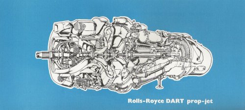
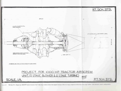
Just thought I would add the very first design scheme that showed the initial layout of Dart.. from RRHT Historical Series No. 18 'The RR Dart pioneering turboprop' by Roy Heathcote. The book is a good description of the development process on the Dart up to the 1980's.
 

Attachments

  • RTS373-first Dart design scheme.jpg
    RTS373-first Dart design scheme.jpg
    185.8 KB · Views: 613
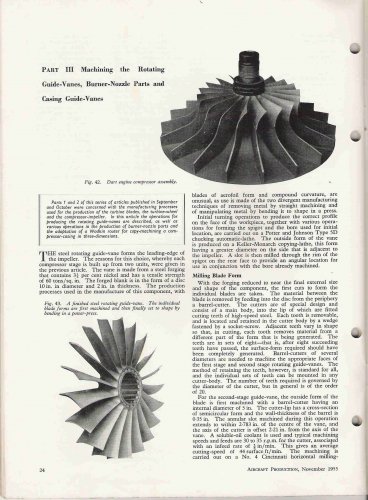
The aerodynamic design Dart centrifugal compressors were based on the experimental results obtained from the latest thinking on the Merlin superchargers. The actual design was based on the characteristics used for the Eagle 22 supercharger design. Translated into hardware the imeller looks like the first picture below, taken from a series of articles on the manufacture of Dart components published in Aircraft Production Sept/Oct/Nov 1955.
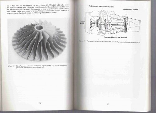
Thirty years after that article RR having spent years making sure the safety and reliability of the Dart were second to none they realised that the 1980's competitors were more efficient (lower sfc) than their offer. An efficiency improvement programme ensued leading to the Mk551 and 552 engines in 1984.
Redesigning the lp impeller within existing casing outlines and then rematching the turbines gave an improvement of 10% on the 551 and a further 3% on the 552. The improvement in compressor efficiency came from incorporating the latest small engine technology from the Leavesden team which was part of the assets acquired when Bristol Siddeley were taken over. RRHT HS18 by Roy Heathcote does in fact contain a great rendition of the Dart story ... I bought a copy last week!... the page showing the Leavesden impeller is below... note the grooved back face and integral RGVs on alternating vanes.
 

Attachments

  • Rolls-Royce Dart- impeller- Aircraft production sept oct NOV 1955-p24.jpg
    Rolls-Royce Dart- impeller- Aircraft production sept oct NOV 1955-p24.jpg
    335.9 KB · Views: 517
  • Rolls-Royce Dart 552 lp impeller-Leavesden style.jpg
    Rolls-Royce Dart 552 lp impeller-Leavesden style.jpg
    212.4 KB · Views: 470
One other thing on my list is the negotiations with DH over production of the gas turbines of MetroVick.. on my next visit to Kew I'll follow this up...unless someone out there already knows what this is about... bearing in mind the Air Ministry's view of how MV treated Armstrong Siddeley!
 
I referred to the Dart compressor design using the latest technology from Leavesden SED; a decade and a half earlier in the late 60s-early 70's SED were facing challenges of their own when trying to develop the centrifugal compressor for the Gem- BS360.
During the same time period AiResearch were facing challenges with ntheir ATF-3 engine. This had a reasonable bypass performance but the core engine had a disappointing performance level. It was agreed that in return for a detail design of the GEM engine RR would redesign the ATF-3 compressor to achieve better core compressor efficiencies. This involved new fan aerodynamics with 30 or 33 blades and resculpting the inner and outer walls of swan neck duct at the rear of the fan hub to reduce losses.. this also involved changing the vane radial aerodynamics to match the new velocity profile. AiResearch carried out a major redesign of the ATF-3 in 1971 to build in RR recommendations as well as other improvements in the light of test bed running of protypes..
 

Attachments

  • AFT3 AirFlow LR.jpg
    AFT3 AirFlow LR.jpg
    142.9 KB · Views: 143
  • Garrett-ATF3.jpg
    Garrett-ATF3.jpg
    102 KB · Views: 384
  • BS gem.jpg
    BS gem.jpg
    55.8 KB · Views: 379
Ah, the ATF-3. I always wanted to place a speech balloon somewhere in the cutaway.

"Hi, I'm an air molecule and I am lost. My mommy said to go to the LPT but I don't (sniffle) know where it is."

The chief engineer was Tony DuPont, who later managed to sell DARPA on the concept of a magic engine that would give you runway-launched SSTO in a 50,000 pound vehicle. DARPA then sold it to Reagan's science advisor, and thus was begotten NASP.

Well, at least NASP was excellent cover for... what's that black Suburban doing outs


CARRIER LOST
 
Reminds me of the 'theory of random walks' p3 of this link describes the process that a confused molecule might take.
 
Hi everyone,

had to register just to say thanks for the great read - or should I say a treasure trove of information!

Altho I do have a question, of sorts: I've been fascinated by the different routes that the German and British jet engine designers took at the time, in particular, the decisions about turbine cooling. I've done some reading on the subject - including the PhD thesis by Giffard mentioned above, which is a fine piece of writing - and know that raw material constraints (apparently, nickel in particular?) had a great impact on the German program, but what I'm trying to find is an explicit answer as to why the Brits didn't use internal cooling until, what, 1952? (RR experiments, mentioned in Gunston's The Development of Jet and Turbine Aero Engines).

I believe and I guess most of the people in the know believe as well that the reason was the ready availability of creep-resistant alloys - they did the job, and cooling was superfluous - but has this been discussed anywhere in more detail?

Also, is anyone aware of any post-war jet engines or turbines that used the "German-style" hollow blades, i.e. either deep drawn or folded and welded from sheet metal? I've had the impression that post-war engines used forged or cast blades, but was that universal?

PS. part of my interest comes from an academic "hobby" - I'm writing a PhD thesis on the effects of constraints and scarcities on innovation. The German hollow blade designs have sometimes been used as an example of an innovation that was born because of the constraint; I'm trying to sharpen that particular theory a bit.
 
The reason the UK did not use turbine blade cooling is because they did not need to! If you consider the thermodynamics of the gas turbine cycle then it becomes obvious that the pressure ratio and top temperature of the engine are related... I'll have to dig out my notes or maybe RR's Gas turbine book has the relevant stuff.... air cooling means bleeding off air for that cooling which reduces the effectiveness of the compressor so one can weigh the economics of pressure needed for the air to flow through the blades, and exhaust into main gas stream and the cost/weight of the turbine blade with and without cooling passages. As we had better materials the need to cool did not need to be addressed until the early fifties when raising the turbine entry temperature and the pressure ratio was the best way to achieve the thrusts needed by the Hunter, etc.
Another way of looking at the problem is to look at the thermal efficiency of an engine and see how the various factors interplay... The equation for thermal efficiency [i.e. (Actual turbine work output- Actual Compressor work input)/(actual heat input) combines the parameters mass flow,temperatures, pressures, fuel/air ratios, compressor bleed flows, component efficiencies, specific heats so one can play with the relative effects of cooling etc.
....I'll scan in my notes on a way of looking at this... when I have found them!
In the meantime here is a page from a Lovesey paper on an interesting way of cooling a turbine!
In the meantime it might be worth looking at 16th Barnwell Memorial Lecture 'Propulsion Prospects' by G. H. Weir on 12 March 1969... RAeS, Fig 1-7 show how the various thermodynamic and material parameters combine.
To sum up WW" German vs British approaches to engine structural innovation:
The Germans had no option; we had options on whether to use blade and vane cooling.
 

Attachments

  • ac lovesey-Scan0129.jpg
    ac lovesey-Scan0129.jpg
    315.6 KB · Views: 114
  • ac lovesey-Scan0130.jpg
    ac lovesey-Scan0130.jpg
    297.4 KB · Views: 128
Exactly. I remember being surprised to look at a Jumo 004 (Science Museum or Dayton, can't remember) and seeing cooling holes.

I also recall being told at P&W, when they were just starting single-crystal blades, that one of the benefits was being able to cast the blade in two halves with a lengthwise split (like the wing of a model kit) which made it possible to cast intricate cooling passages into the mating surface, and thus get better cooling without using more air.
 
tartle said:
The reason the UK did not use turbine blade cooling is because they did not need to! If you consider the thermodynamics of the gas turbine cycle then it becomes obvious that the pressure ratio and top temperature of the engine are related... I'll have to dig out my notes or maybe RR's Gas turbine book has the relevant stuff.... air cooling means bleeding off air for that cooling which reduces the effectiveness of the compressor so one can weigh the economics of pressure needed for the air to flow through the blades, and exhaust into main gas stream and the cost/weight of the turbine blade with and without cooling passages. As we had better materials the need to cool did not need to be addressed until the early fifties when raising the turbine entry temperature and the pressure ratio was the best way to achieve the thrusts needed by the Hunter, etc.
Another way of looking at the problem is to look at the thermal efficiency of an engine and see how the various factors interplay... The equation for thermal efficiency [i.e. (Actual turbine work output- Actual Compressor work input)/(actual heat input) combines the parameters mass flow,temperatures, pressures, fuel/air ratios, compressor bleed flows, component efficiencies, specific heats so one can play with the relative effects of cooling etc.

Excellent explanation, thank you! Exactly the answer I was looking for :). If you manage to scan your notes, they would be much appreciated as well!

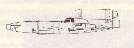
One question, though: is it absolutely necessary to use compressor bleed air for cooling? I (of course) read Antony Kay's book "German jet engine development 1930-1945," and there is a mention about Porsche 109-005 "disposable" jet engine, intended for longer-ranged V-1's. The text mentions that the turbine blades had internal cooling as per BMW 003's, but that the cooling air was not ducted from the compressor; instead, it was scooped via simple inlet. I would guess that this would be adequate given the short lifetime of the missile, but problematic with larger engines intended for aircraft?
 
jmkorhonen said:
One question, though: is it absolutely necessary to use compressor bleed air for cooling?

It helps to have a think back to the gas turbine cycle. The compressor compresses the air so that the highest pressure air is at the end of the compressor just before entering the combustion chamber. Heat is then added and the air is expanded through the turbine. Whilst the air is running through the turbine, the pressure is decreasing.

The turbine stage next to the combustion chamber will require the most cooling airflow, but because of the proximity to the combustion chamber, the air pressure is still high. Hence, a higher pressure cooling air source is required in order to overcome the air pressure at the turbine. Connecting the turbine cooling holes with the atmosphere would result in hot air from the turbine escaping to the atmosphere - exactly the opposite of what is required.

I'm surprised about your mention of the 005 engine having an external ram scoop for cooling air. I could concieve that this would possibly work if the engine flew fast enough and had a very low pressure ratio, but this makes for very poor fuel efficiency - not that this is necessarily required for a disposable engine.
 
Interesting!

I have to double check Kay's book as to where exactly the cooling air was piped in, but I do remember it was not from the compressor and that the centrifugal "suction" in the turbine was believed sufficient to maintain cooling air flow necessary for short lifetime of the engine. I honestly hadn't thought about back flow - somehow I visualized that the internal blade cooling (as opposed to, what's it called, air film cooling?) would be sealed from the hot gases. Now that I think of it, the sealing problems would seem to be formidable, though!

Thanks again, this is exceedingly useful input for someone with a little bit of technical literacy but zero experience in turbomachinery. I'm working on a paper that may or may not be published in some scholarly journal, but if you're interested, I'd very much like to put a draft online for your comments and inevitable corrections :D.
 
You can have internal air cooling but at some point it will exhaust into the hot gas stream so one needs at least that pressure.. possibly enough to keep the impulse blades cool enough for a V1 flight:

"There were development programs at both BMW and Porsche for disposable
turbo-jet versions. These were to double the range, simplify starting
and launch procedures as well the lack of vibration was expected to
significantly improve accuracy due to the interference of the
vibrations with the compass and odometer which was simply a prop
driving a 30:1 gearbox with a nut on a threaded rod opperating the
cutout switches.

The BMW version, known as the P.3307 (A BMW project number) had a mild
steel hollow turbine blade design capable of a life of 2 hours. The
Porsche version which had the RLM designation 109-005 had a geared
first stage compressor, which sounds complicated for a dispossable
systems but it was thought to help efficiency and provide for shedding
of ice. In the Porsche version air through the turbines was not from
the compressor but simply ram air. The compressors were impulse type
axials because these were easier to produce than centrifugals or
reaction type axials."

We would need to pick up pressure in the cooling passages to ensure pressures were high enough to exhaust and not allow hot gas in.

you are right that single crystal blades were originally made in two pieces to get a comples cooling passge in. but one can anyway in a conventional cast blade ...columnar crystals and single crystal structures are then only a question of technique so eliminating the joining of two pieces... but that is another story!
If someone can scan the relevant page of what the Porsche looked like we can think more clearly about all this.
 

Attachments

  • reichenberg.jpg
    reichenberg.jpg
    12.5 KB · Views: 107

Similar threads

Please donate to support the forum.

Back
Top Bottom